Description
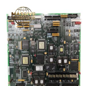
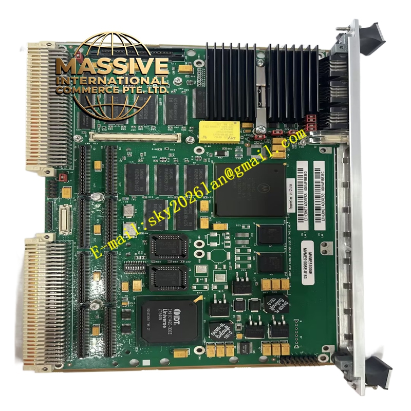
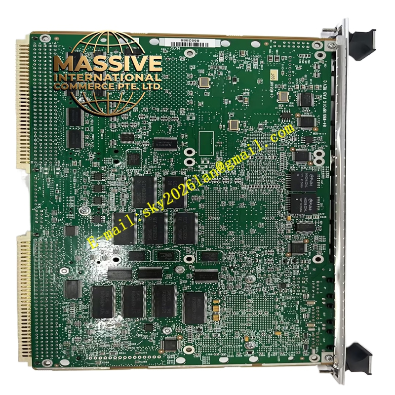
GE MVME51005E-0163
Technical Specifications:
- Series: Motorola MVME5100
- Processor: MPC7410, MPC750, or MPC755 class microprocessor
- L1 Cache: 32 KB instruction / 32 KB data
- L2 Cache: Up to 2 MB backside secondary cache
- Front-Side Bus: 100 MHz
- Memory: Up to 512 MB on-board ECC SDRAM (expandable to 1 GB with optional RAM500 memory expansion modules)
- Flash Memory: 17 MB (16 MB + 1 MB)
- NVRAM: 32 KB with time-of-day clock and replaceable battery backup
- Ethernet: Dual 10BaseT/100BaseTX Ethernet interfaces (82559ER controllers)
- Serial Ports: Dual 16550-compatible asynchronous serial ports
- PMC Slots: Dual IEEE P1386.1 compatible 32/64-bit expansion slots
- PCI Expansion: 64-bit mezzanine connector allowing up to four additional PMCs
- Timers: Four 32-bit timers and one watchdog timer
- VMEbus Interface: VME Universe II B ASIC
- Connectors: P1 and P2 for VMEbus interface, RJ-45 for Ethernet and serial
- Operating Temperature: 0 °C to 55 °C (commercial), -20 °C to +71 °C (extended)
- Dimensions: Standard single slot even when fully configured with two PMC modules
- On-Board Debug Monitor: PPCBug firmware
Functional Features:
- PowerPlus II architecture with memory read bandwidth of 582 MB/s and burst write bandwidth of 640 MB/s
- Full PCI throughput of 264 MB/s without starving the processor from its memory
- Dual expansion slots with front and rear I/O capability
- 64-bit expansion mezzanine connector for up to four additional PMC modules
- Extended temperature versions available (-20 °C to +71 °C) for harsh environments
- Hardware and software compatible across MVME5100 product versions
- ECC SDRAM for data integrity
- On-board debug monitor (PPCBug) for diagnostics and configuration
Application Scenarios:
- Defense and aerospace: mission computing, signal processing, radar systems
- Industrial automation: high-performance embedded control and data acquisition
- Medical imaging: diagnostic equipment image processing
- Telecommunications: network control and protocol processing
- Test and measurement: high-bandwidth data acquisition and analysis
Performance Parameters:
- Supercomputing-level performance in a single VME slot
- High memory bandwidth (582 MB/s read, 640 MB/s burst write)
- Full 264 MB/s throughput without processor memory starvation
- Scalable memory up to 1 GB with expansion modules
- Single VME slot occupancy even with dual PMC and dual memory mezzanines
Material and Structural Characteristics:
- Standard form factor PCB with PowerPlus II architecture ASIC
- Hawk PCI bridge-memory controller ASIC
- VME Universe II B VMEbus interface ASIC
- Dual RJ-45 connectors for Ethernet and serial ports
- Metal front panel with ejector levers and status indicators
- Replaceable battery for NVRAM and RTC backup
Working Principle: The MPC7410/750/755 processor executes application code from ECC SDRAM, communicating with peripherals via the bus. The Hawk ASIC serves as the PCI bridge-memory controller, optimizing memory bandwidth and decoupling the processor from traffic. The VME Universe II B ASIC provides the VMEbus interface, supporting master and slave operations. expansion slots connect through the PCI bus, enabling application-specific I/O customization. The PPCBug firmware provides boot, debug, and diagnostic capabilities. Installation Requirements:
- Install in a standard VMEbus chassis with compatible backplane
- Configure jumper settings per the hardware preparation manual
- Align P1 and P2 connectors and seat the board fully using ejector levers
- Secure with front-panel mounting screws
- Connect Ethernet, serial, and PMC I/O cables
- Use PPCBug commands for initial configuration and memory mapping
Usage Notes:
- Verify processor type and speed match the application requirements
- Replace the NVRAM backup battery periodically to maintain RTC and stored data
- Observe ESD precautions during handling and installation
- Confirm PMC module compatibility with the 32/64-bit slots
- Use the PPCBug CNFG and ENV commands for board configuration
- Refer to the memory mapping documentation for application development