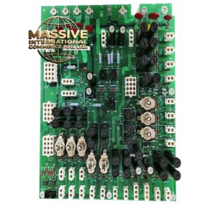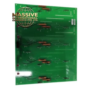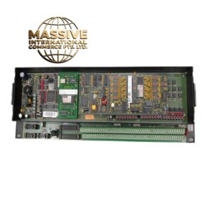
Description
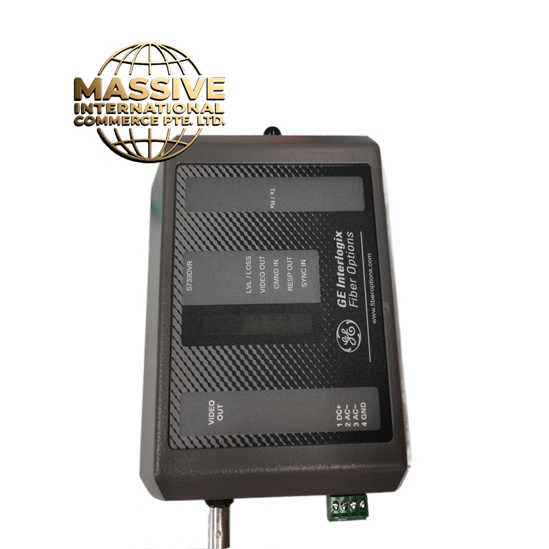
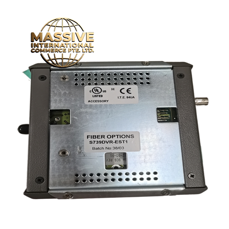
GE S739DVR0
Technical Specifications
| Parameter | Specification |
|---|---|
| Function | Digital Input Signal Interface |
| System Compatibility | GE PLC and DCS systems |
| Input Type | Digital (Binary) |
| Number of Channels | Multiple channels (configuration dependent) |
| Voltage Rating | 24V DC standard industrial level |
| Signal Type | Dry contact or voltage-free inputs |
| Communication Protocol | Modbus, Ethernet/IP, proprietary GE protocols |
| Isolation | Channel-to-channel electrical isolation |
| Environmental Rating | Industrial grade, dust and moisture resistant |
| Mounting | DIN rail mounting |
| Operating Temperature | 0°C to 60°C (32°F to 140°F) |
| Storage Temperature | -40°C to 85°C (-40°F to 185°F) |
| Humidity | 5% to 95% non-condensing |
Functional Features
-
High Precision Detection: Accurate and reliable detection of digital signals with minimal false readings
-
Fast Response Time: Real-time monitoring and control with quick processing of input changes
-
Electrical Isolation: Channel-to-channel isolation to prevent interference and enhance safety
-
Built-in Diagnostics: Self-monitoring functions to detect module health and wiring faults
-
Configuration Flexibility: Customizable settings for input filtering, debounce, and other parameters via software tools
-
Wide Voltage Compatibility: Supports standard industrial voltage levels
-
Status Indication: LED indicators for channel status and module health
Structural Characteristics
-
Compact modular design for space-efficient installation
-
Rugged industrial-grade housing
-
Removable terminal blocks for easy wiring and maintenance
-
Conformal coated PCB for moisture and chemical resistance
-
DIN rail mounting clip for quick installation
-
Status LED array for visual indication of all channel states
Working Principle The module receives digital signals from field devices such as limit switches, push buttons, proximity sensors, and relay contacts. Each input channel includes signal conditioning circuitry that filters electrical noise and debounces mechanical switch contacts. The conditioned signals are then read by an internal microprocessor which communicates the input states to the main PLC or DCS controller via the system backplane or network interface. Input filtering and debounce parameters are configurable to accommodate different types of field devices and operating conditions.
Installation Requirements
-
Mount on standard DIN rail in control cabinet
-
Connect field wiring to removable terminal blocks
-
Configure input parameters using GE programming software
-
Ensure proper grounding of module and shield connections
-
Maintain separation between input signal cables and power cables
-
Verify correct voltage levels before applying power
Application Scenarios
-
Manufacturing plant machinery monitoring and control
-
Power plant switchgear and breaker status monitoring
-
Oil and gas pipeline valve position monitoring
-
Water treatment pump and valve control
-
Building automation HVAC and lighting control
-
Conveyor system position and safety interlock monitoring
Usage Precautions
-
Verify correct input voltage levels before connection
-
Ensure proper grounding to prevent ground loop issues
-
Do not exceed rated input voltage specifications
-
Use shielded cables in high-noise environments
-
Regular inspection of terminal connections for corrosion
-
Follow ESD handling procedures during installation