Description
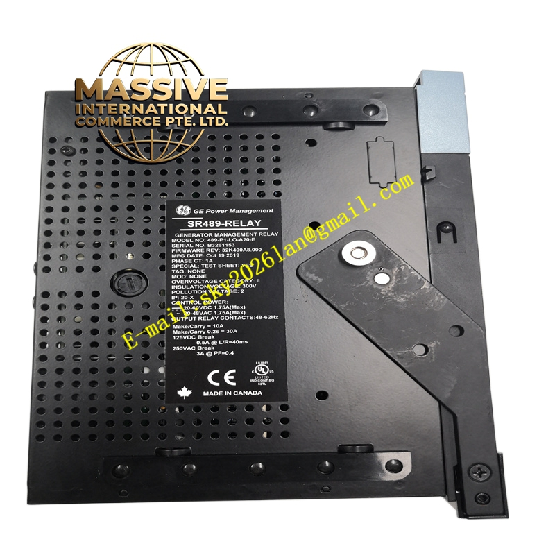
GE SR489-P1-LO-A20-E
Technical Specifications:
- Series: GE Multilin SR489 Generator Management Relay
- Phase CT Secondary: 1 A (P1)
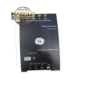
- Control Power: LO = 20–60 V DC, 20–48 V AC, 48–62 Hz
- Analog Output: 4–20 mA (A20)
- Display: Enhanced (E) with larger LCD
- Communication: RS-232, RS-485/RS-422
- Fuse Rating: 2.5 A, 5×20 mm HRC SLO-BLO Littelfuse 215-02.5
- Software: EnerVista 489 Setup
- Conformal Coating: No (standard environment)
Functional Features:
- Comprehensive generator protection: differential, overcurrent, overvoltage, undervoltage, overfrequency, underfrequency, loss of field, reverse power, negative sequence, stator ground fault, breaker failure, VT fuse failure
- Enhanced display with larger LCD for local diagnostics
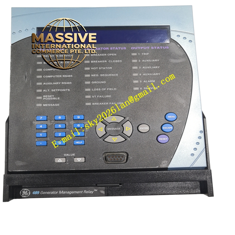
- Output status LEDs: 1 trip, 2 auxiliary, 3 auxiliary, 4 auxiliary, 5 alarm, 6 service
- Generator status LEDs: breaker open, breaker closed, stator overheat, negative sequence, ground, loss of field, VT fault, breaker failure
- 489 status LEDs: 489 in service, setpoint access, computer RS232, computer RS485/aux RS485, alternate setpoint, reset, message
- Flash memory for firmware upgrades
- Simulation, trip coil monitoring, breaker failure, drawout case
- Metering: user-programmable analog inputs, RPM (with keyphasor input), RTD, power factor, frequency, MW, Mvar, ±MVarh demand, apparent power and MVA demand, actual power, MW demand, MWh, current (phasor) and ampere demand, voltage (phasor)
Application Scenarios:
- Generator protection in power plants
- Industrial cogeneration facilities
- Diesel and gas generator backup systems
- Hydroelectric and wind generator protection
- Any application requiring comprehensive generator management
Performance Parameters:
- Comprehensive metering of generator electrical parameters
- Fast-acting protection elements for generator fault clearance
- Enhanced display improves local diagnostic visibility
- Flash-upgradable firmware for feature updates
Material and Structural Characteristics:
- Drawout relay case with matching enclosure (SR construction)
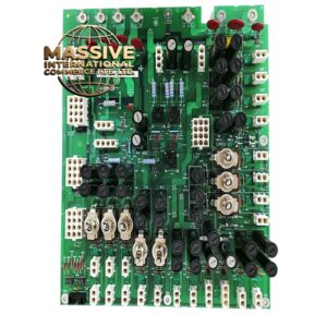
- Industrial-grade PCB with high-reliability components
- Front panel with enhanced LCD, output status LEDs, generator status LEDs, 489 status LEDs, keypad
- RS-232 port on front panel; RS-485/RS-422 on rear panel
- Rear terminal blocks for CT, VT, control power, and I/O
- Fuse holder (2.5 A, 5×20 mm HRC SLO-BLO)
Working Principle: The relay continuously samples generator phase currents (1 A CT secondary), voltages, and field signals. The on-board processor executes protection algorithms for differential, overcurrent, over/under-frequency, loss of field, reverse power, negative sequence, and stator ground fault protection. When a protection element operates, the relay energizes output contacts to trip the generator breaker. Status LEDs provide immediate visual indication of generator and relay state. Event records and oscillography are stored for post-fault analysis. Installation Requirements:
- Install in a protection relay panel using the SR drawout case
- Connect 1 A phase CTs, VTs, and ground CT per schematics
- Wire control power (20–60 V DC or 20–48 V AC)
- Connect RS-232/RS-485 to SCADA
- Configure setpoints using EnerVista 489 Setup software
- Verify fuse (2.5 A, 5×20 mm HRC SLO-BLO Littelfuse 215-02.5) is installed
Usage Notes:
- Relay contacts are not safe to touch when energized; ensure proper insulation for low-voltage accessible applications
- Verify CT secondary rating (1 A) matches installed CTs
- Use EnerVista 489 Setup software for configuration and firmware upgrades
- For harsh environments, consider the -H conformal-coated variant
- Periodically test protection functions using a relay test set