Description
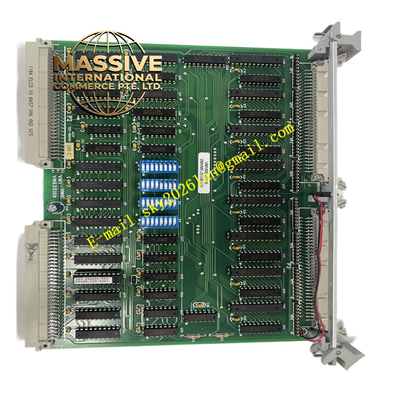
GE VMIVME-2532A
- Technical Specifications (typical per VMIC 2500/3500 families):
- I/O count: 32 or 64 channels (mix of inputs/outputs; verify with datasheet)
- Input type: Opto-isolated, 24 V DC typical, support for dry contact or wetting voltage
- Output type: Isolated open-collector or relay outputs; current ratings per channel (e.g., 500 mA max)
- Isolation voltage: 1000 V–2500 V RMS channel-to-ground (typical)
- VME interface: A24/D16 or D32, interrupter capability
- LED indicators: Per-channel status LEDs on front panel
- Functional Features:
- High-density digital interfacing in a single VME slot
- Optical isolation protects the system from field transients and ground loops
- Per-channel LEDs simplify troubleshooting
- Application Scenarios:
- Machine control and interlocking panels
- Industrial test fixtures and automated test equipment
- Process control digital status monitoring and actuation
- Performance Parameters:
- Fast response times suitable for high-speed logic and safety interlocks
- Robust isolation ensures reliability in electrically noisy environments
- Material and Structural Characteristics:
- 6U VME board with front-panel connectors (terminal blocks or high-density headers)
- Industrial-grade optocouplers and output drivers; conformal coating options
- Working Principle: Reads the state of opto-isolated inputs and presents them to VME memory; writes to output registers drive isolated outputs (open-collector or relay). Interrupts can be generated on input state changes.
- Installation Requirements:
- Mount into a 6U VME chassis; verify backplane voltage and current budget
- Wire field devices to front-panel terminals following polarity and current limits
- Configure input/output polarity and debounce settings per application
- Usage Notes:
- Do not exceed maximum output current per channel and total module limits
- Use fusing where inductive loads are driven to protect the board
- Ensure proper grounding of field shields to maintain isolation integrity