Description
GE XGF868I-1-1-OI-H-3-4-0-CC Technical Specifications:
- Product Series: GE DigitalFlow XGF868i (flare gas ultrasonic flowmeter)
- Measured Fluid: Flare gas, vent gas, hydrocarbon gases, biogas, digester gas
- Measurement Principle: Correlation Transit-Time ultrasonic technology
- Pipe Compatibility: All metal, fiberglass; other materials on request (Panametrics)
- Flow Accuracy (Velocity): Dependent on pipe diameter and gas type
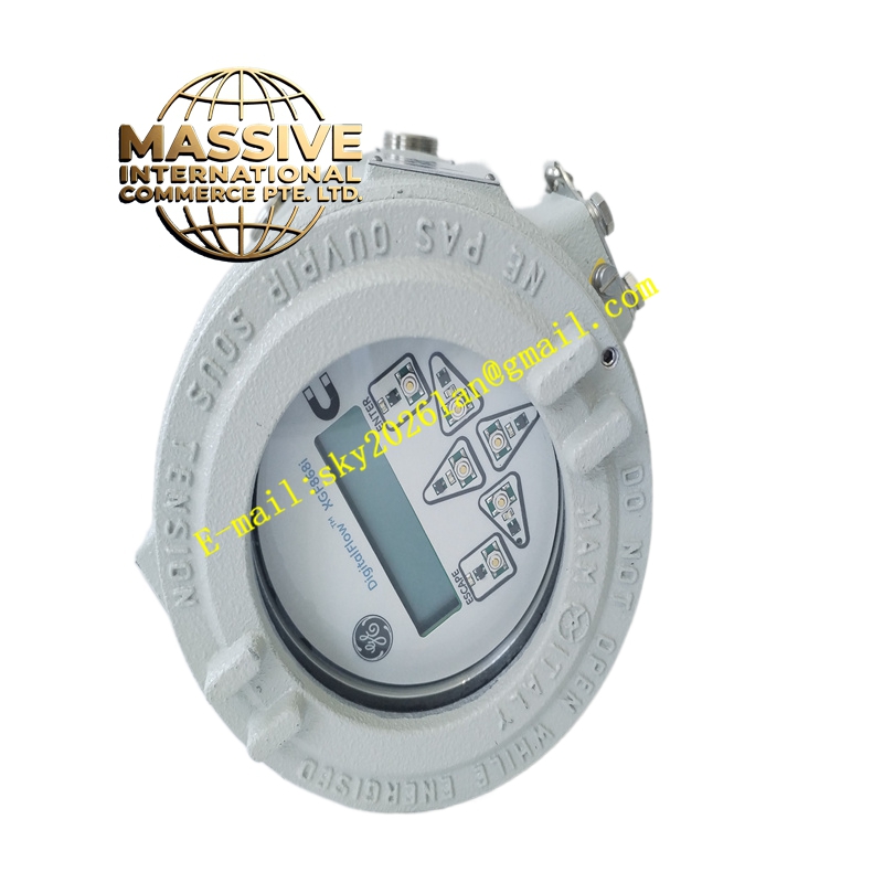
- Display: 2 lines × 16 characters backlit LCD, configurable to display up to four measurements sequentially
- Keypad: Built-in magnetic keypad for local operation
- Outputs (Standard): 4–20 mA, digital interface RS-232 (for PanaView PC software), HART 7 protocol
- Communication Options: Modbus RS-485 or TCP/IP; Ethernet; OPC server; Foundation Fieldbus; NAMUR NE107 compliance (selected via options)
- Approvals: Hazardous area certifications (option-dependent; consult datasheet for specific ATEX/IECEx/ FM details)
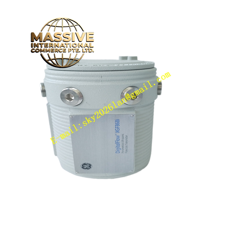
- Housing: Compact, explosion-proof/fire-rated transmitter enclosure; installed near the flow measurement point
- Power Supply: Typically 24 V DC (or per specific configuration)
- Environmental: Industrial; temperature and humidity ratings per datasheet
Functional Features:
- Correlation Transit-Time technology with digital signal processing ensures high accuracy and fast response
- Precise molecular weight calculation supports accurate measurement of variable-composition flare gas
- Minimal maintenance requirements due to non-intrusive ultrasonic sensors (no moving parts)
- Wide rangeability suitable for varying flare loads and low-velocity conditions
- Magnetic keypad allows safe operation without opening the enclosure in hazardous areas
- Multi-protocol communication facilitates integration into DCS/SCADA systems (HART, Modbus, Ethernet, OPC, FF)
- Configurable LCD shows multiple parameters for local indication
- Supports advanced applications: net heating value (NHV) measurement, mass balance accounting, proportional flare control, regulatory compliance, and energy saving
Application Scenarios:
- Refinery and petrochemical flare gas measurement and reporting
- Oil and gas production flare and vent gas flow measurement
- Landfill biogas and digester gas flow measurement
- Power plant flue gas and vent monitoring
- Regulatory compliance and emissions reporting
- Steam-saving proportional flare control and energy management
Performance Parameters:
- High accuracy over a wide flow range; exact accuracy depends on pipe size and gas properties
- Fast response to changes in flow and gas composition
- Wide rangeability (turndown) supports low-flow and high-flow conditions
- No pressure drop across the measurement section
- Suitable for wet and dirty gas due to ultrasonic transit-time measurement
Material and Structural Characteristics:
- Transmitter Housing: Explosion-proof/fire-rated metal enclosure (stainless steel or aluminum)
- Sensor Spool: Fabricated from pipe material matching the process (carbon steel, stainless steel, or fiberglass)
- Ultrasonic Transducers: Robust, hermetically sealed; wetted materials compatible with measured gas
- Cabling Entries: Sealed conduit or cable glands for hazardous areas
- Display Window: Laminated glass or polycarbonate with backlight
Working Principle: Pairs of ultrasonic transducers mounted on the sensor spool transmit and receive ultrasonic signals along diagonal paths through the gas. The XGF868i measures the transit times in both directions and uses correlation techniques to compute gas velocity independently of speed of sound variations. Combined with pressure and temperature inputs (when used), and with molecular weight calculation, it calculates standardized volumetric flow, mass flow, and energy flow. The transmitter outputs 4–20 mA signals and digital data via HART, Modbus, or Ethernet, and displays measured values locally. Installation Requirements:
- Install the sensor spool in a horizontal or vertical pipe run with sufficient straight run upstream and downstream (per installation manual)
- Mount the transmitter close to the spool or remotely as required, ensuring hazardous area approvals match the site classification
- Connect power, signal, and communication wiring using approved glands and shielded cables
- Provide pressure and temperature inputs if mass or energy flow calculation is required
- Ground and bond the sensor spool and transmitter per plant standards
Usage Notes:
- Verify that the pipe material, diameter, and gas composition are compatible with the configuration and calibration
- Perform zero and span checks per the manual during commissioning and after maintenance
- Use the magnetic keypad for configuration; avoid strong external magnetic fields during operation
- Ensure conduit entries remain sealed and gaskets are intact to maintain hazardous area integrity
- Regularly inspect transducer faces and spool interior for buildup or condensation; clean as needed
- Keep firmware and communication module configurations up to date; use only GE-approved software and cables