



Description
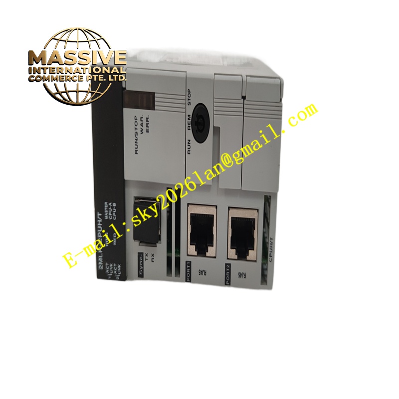
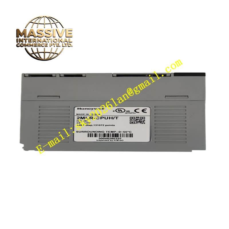
Honeywell 2MLR-CPUH/T
Technical Specifications High-speed real-time embedded processor; on-board RAM and non-volatile flash memory; hardware watchdog circuit; backplane I/O bus interface; network communication port for SCADA and HMI connection; powered by 24V DC backplane supply; supports redundant master-backup operation.
Functional Features Runs user control programs including PID regulation, sequential control and safety interlock logic. Reads process signals from I/O modules and outputs control commands to field devices. Synchronizes real-time data and alarm events to the supervisory system. The hardware watchdog resets the processor automatically if program execution fails. Supports online program downloading without halting critical control functions when configured appropriately. Redundant pairs perform bumpless switchover upon primary module failure.
Application Scenarios Oil and gas processing plants, chemical facilities, power generation auxiliary systems and manufacturing plants adopting Honeywell Master Logic control platforms.
Performance Parameters Fixed control execution cycle; fast interlock response; stable network data throughput; seamless redundant switchover.
Material Composition PCB substrate is FR-4 high-speed flame-retardant multilayer material; processor and memory chips are industrial wide-temperature components; backplane connector contacts are gold-plated; front panel is flame-retardant PC material.
Structural Characteristics Rack plug-in CPU card; front panel equipped with LED indicators for run status, fault status and network communication; rear gold fingers connect to the control rack backplane; anti-keying positioning pins prevent reverse installation; mounting screw holes secure the card inside the controller rack.
Working Principle After power-up, the module completes self-diagnosis and loads stored control logic and parameters. It cyclically acquires field data from I/O modules, executes control algorithms and sends output instructions to I/O cards. Real-time values and alarm records are packaged and transmitted to HMI and supervisory hosts over the communication network. In redundant configurations, the backup CPU synchronizes all data continuously and takes over control instantly once the primary unit fails.
Installation Requirements Perform installation with cabinet power disconnected and implement anti-static measures. Insert the module into the dedicated CPU slot and fasten mounting screws. Connect communication cables following Honeywell cabling specifications. Download control programs from the engineering workstation and verify redundant switchover functions.
Precautions for Use Hot plugging of the CPU module is forbidden. Back up all control logic and parameters before program modification. Inspect network cables and terminating resistors if communication loss occurs. Store spare modules in anti-static shielding bags.







