



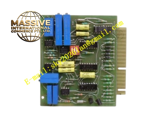
Description
Honeywell 51109620-080
Technical Specifications Multi-slot rack backplane; Supports TPS series controller and I/O modules; Rated operating voltage 5V, 24V DC; Operating temperature range 0°C to +60°C; Relative humidity 5% to 95% non-condensing; Gold plated connector contacts; Multi-layer PCB design; Rack mounted structure.
Functional Features Distributes system DC power to each rack slot; Transmits high-speed parallel backplane bus signals; Provides mechanical positioning and locking interface for inserted modules; Isolates power traces and signal traces to reduce electromagnetic interference; Supports hot swap for qualified I/O cards; Built-in circuit protection against overcurrent and short circuit; Maintains long-term signal integrity for continuous plant operation.
Application Scenarios Petrochemical TDC3000 DCS control cabinet; Refinery process control rack; Power plant boiler control system; Chemical reactor monitoring control cabinet; Pulp and paper mill distributed control system; Pharmaceutical batch process control rack.
Performance Parameters Gold contact resistance maintains low stable value; Signal transmission delay keeps consistent across all slots; Power distribution ripple stays within rated range; Withstands repeated thermal cycling without contact degradation; Bus signal noise suppression meets industrial EMC standards.
Material Composition FR4 multi-layer flame retardant printed circuit board; Gold plated copper contact pins; Copper conductive traces; Epoxy resin substrate; Plastic rack positioning baffle; Metal fixing brackets; Screw mounting hardware.
Structural Features Flat rectangular backplane board; Multiple card slot edge connectors arranged linearly along front edge; Power and signal traces embedded in PCB layers; Mounting holes distributed across board surface for rack fastening; Separate power region and signal region layout to avoid cross interference.
Working Principle External rack power supply feeds DC power to power traces on backplane. When modules insert into rack slots, gold plated contacts mate with module edge connectors. Control and data signals transfer between controller card and each I/O module through dedicated bus traces on PCB. The backplane routes all parallel digital signals and distributes power simultaneously. Isolation layout prevents crosstalk between adjacent module channels.
Installation Requirements Mount backplane securely inside standard DCS rack with specified torque for mounting screws; Verify no debris or conductive particles on contact surface before card insertion; Route rack power cables according to wiring diagram; Ensure proper cabinet protective earth connection; Maintain cabinet ventilation to keep operating temperature within limits.
Precautions for Use Cut off rack main power before backplane replacement; Prevent electrostatic discharge damage to PCB and gold contacts; Do not bend or scratch gold plated contact pins; Keep cabinet internal environment dry to avoid condensation; Inspect contact condition periodically after long-term operation.







