



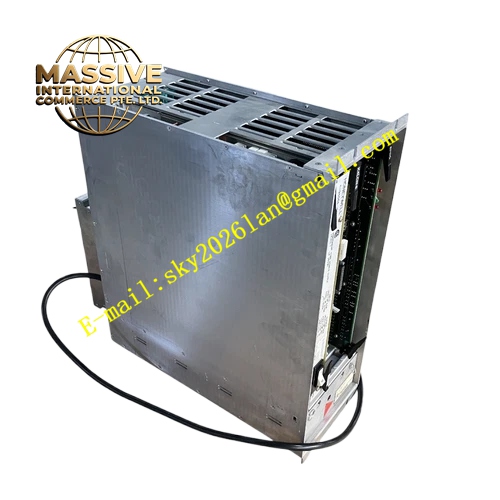
Description
Honeywell 51109701-100
Technical Specifications
- Processor: 32-bit industrial processor
- Memory: Onboard flash for firmware and configuration, SRAM for runtime data
- Backplane Bus: TDC 3000 proprietary backplane control bus
- Power Supply: 5VDC and 12VDC from rack backplane
- Operating Ambient Temperature: 0°C to +60°C
- Storage Temperature: -40°C to +85°C
- Relative Humidity: 5% to 90% RH non-condensing
- Mounting Method: Plug-in slot installation on TDC 3000 rack
- Certification: UL, CE, RoHS
Functional Features It runs deterministic control strategy with fixed execution cycle. It supports PID, cascade, feedforward, ratio and custom interlock algorithms. It processes field I/O data from analog and digital paddle cards. It supports 1:1 redundant pairing with second identical processor board for bumpless switchover. It connects to TDC 3000 LCN network via LCN interface board. It provides comprehensive self-diagnosis including memory error, bus timeout, watchdog fault and firmware exception. It supports hot swap replacement in redundant rack configuration. It records alarm event log and process trend data. It supports online download, parameter modification and point force operation from TDC 3000 engineering workstation. It receives unified clock tick signal from clock source board.
Application Scenarios Large petrochemical plant TDC 3000 central DCS control cabinet Refinery distillation and cracking unit control node Chemical plant continuous process and batch reactor control Power plant boiler, turbine and auxiliary system TDC 300 control rack Natural gas liquefaction plant legacy DCS control node
Performance Parameters
- Configurable Control Cycle: 50ms to 5000ms
- Mean Time Between Failures: 890000 hours
- Insulation Resistance: Greater than 1000 MΩ
- ESD Immunity: 8kV contact discharge
- Maximum Supported I/O Points: Matched with TDC 3000 node specification
Material Composition FR4 conformal coated multilayer flame retardant PCB 32-bit industrial processor chip Flash memory and SRAM chips Backplane bus transceiver chips Watchdog fault monitoring circuit Gold plated edge connector for rack backplane Metal front panel with extraction handle and multi-color LED indicators Metal locking buckle
Structural Features Standard TDC 3000 rack plug-in paddle card form factor. Front panel integrates power, run, fault and communication LED indicators and extraction handle. Rear gold finger connector connects to rack backplane power, control bus and clock bus. Internal PCB layout separates high-speed processor circuit and low voltage I/O bus circuit to reduce electromagnetic crosstalk. Anti-key notch prevents reverse insertion into rack slot. Locking clip secures module firmly after installation. Internal shielding suppresses interference from adjacent I/O and communication cards.
Working Principle After power on, the module completes power-on self-test and initializes backplane bus communication. It loads control strategy downloaded from TDC 3000 engineering station into runtime memory. It reads field I/O value from I/O paddle cards every control cycle. It executes configured control algorithms and calculates output command to field actuators. It uploads process variable, alarm and diagnostic status to LCN network and operator station. In redundant configuration, runtime data is synchronized continuously between paired processor boards. When active processor fault occurs, standby unit takes over control without process disturbance. Diagnostic circuit uploads fault event to operator station.
Installation Requirements Wear anti-static wrist strap before installation. Insert module into designated processor slot of TDC 3000 rack and lock front handle. Complete controller address, redundancy and LCN network configuration in TDC 3000 engineering software. Download matching control strategy and parameter set. Power on rack and wait for run LED steady on. Verify communication status with I/O paddle cards and LCN network. Test redundancy switchover function manually and confirm bumpless transfer.
Usage Notes Do not insert the module into non-processor rack slot. Keep anti-static protection during transportation and replacement. Do not power cycle rack during online control strategy download. Back up configuration file before module replacement. Do not open module housing or modify internal components.







