



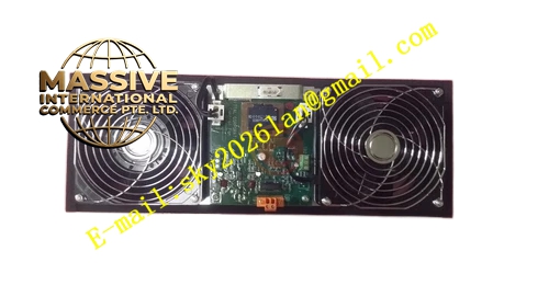
Description
Honeywell 51303940-250
Technical Specifications
- Brand: Honeywell
- Part Number: 51303940-250
- Product Type: Cabinet fan module / cooling fan assembly
- Application: Honeywell DCS or industrial control cabinet cooling
- Function: Forced ventilation and thermal management
- Alarm Function: Fan fault detection and alarm support
- Typical Cabinet Temperature Target: Around 0 °C to 40 °C, depending on system requirements
- Weight: Approximately 1.1 kg
Functional Features
- Provides forced convection cooling for control cabinets.
- Helps remove heat from controllers, power supplies, and I/O cards.
- Maintains more uniform cabinet temperature distribution.
- Reduces local hot spots inside the control cabinet.
- May support fan fault alarm output to the control system.
- May include redundant fan design for continued operation after a single fan failure.
- Works with intake filters to help maintain cabinet cleanliness.
- Supports reliable long-term operation of industrial control hardware.
Application Scenarios
- Honeywell DCS control cabinets.
- Industrial automation control rooms.
- Process control system racks.
- Power supply and controller cabinet cooling.
- Replacement of failed cabinet fan assemblies.
- Preventive maintenance for critical control systems.
Performance Parameters
- Provides continuous cabinet ventilation.
- Supports fault detection and alarm signaling for fan failure.
- Helps maintain cabinet temperature within the manufacturer-specified range.
- Typical operating environment for protected cabinets is around 0 °C to 40 °C.
- Exact supply voltage, airflow rate, fan speed, noise level, dimensions, mounting hole pattern, and alarm interface should be confirmed from the module nameplate and official documentation.
Material Composition
- Fan housing
- Motor and impeller assembly
- Electrical wiring and connector
- Mounting frame
- Protective grille or filter interface
- Fault detection circuit
- Label with part number and revision
Structural Features
- Modular fan assembly designed for cabinet installation.
- Typically arranged to support bottom cold-air intake and top hot-air exhaust.
- May include dual fans for redundancy.
- Integrates with cabinet filter assemblies to reduce dust ingress.
- Provides an alarm signal when fan speed is abnormal or a fan stops.
- Exact dimensions, fan count, airflow direction, and connector type depend on the specific cabinet platform.
Working Principle
The 51303940-250 fan module draws cooler air into the cabinet and expels heated air, creating continuous airflow across controllers, power supplies, and I/O modules. This airflow prevents localized overheating and helps keep internal cabinet temperature within the allowed range. If a fan stops or its speed falls below the expected level, the module generates a fault signal so the control system or operator can take corrective action before equipment overheats.
Installation Requirements
- Confirm the cabinet model and fan module compatibility.
- Disconnect cabinet power before installation.
- Follow lockout/tagout and electrical safety procedures.
- Verify correct airflow direction before final mounting.
- Ensure intake filters are clean and properly installed.
- Secure all mounting fasteners to prevent vibration.
- Reconnect the fault alarm wiring if applicable.
- Test fan operation and alarm function after installation.
Precautions for Use
- Do not block air intake or exhaust openings.
- Replace clogged filters regularly to maintain airflow.
- Do not operate the cabinet with missing or damaged fans.
- Investigate fan fault alarms immediately.
- Keep the cabinet door closed during normal operation.
- Avoid installing the module in wet, dusty, or corrosive environments unless the cabinet is properly rated.







