



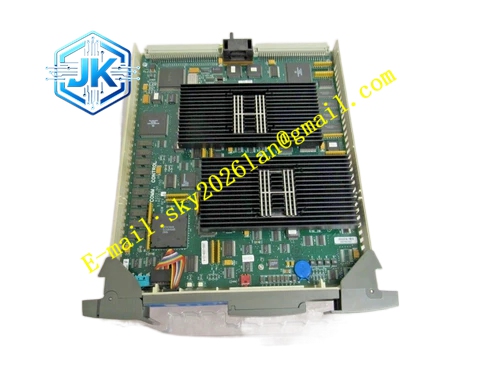
Description
Honeywell 51402610-200
Technical Specifications Time Base Source: On-board high precision temperature compensated crystal oscillator Time Synchronization Precision: ±0.5ms Time Frame Broadcast Cycle: 1 second LCN Interface: 5Mbps coaxial bus, BNC connectors Power Supply: 5V DC Power Consumption: 4.2W Operating Temperature Range: 0℃ to 65℃ Storage Temperature Range: -40℃ to 85℃ Isolation Withstand Voltage: 1500V AC Relative Humidity: 5% to 95%, non-condensing
Functional Features It maintains continuous calendar and clock counting including year, month, day, hour, minute and second. It supports manual time calibration from GUS operator station. It executes automatic crystal oscillator drift compensation to reduce long-term time deviation. It supports redundant master clock configuration and automatic clock source switching. It stores time calibration records and clock fault log data in non-volatile memory. It uploads clock drift, synchronization frame loss and module fault alarm to LCN network diagnostic console. It distributes unified time stamp to all LCN and UCN nodes.
Application Scenarios Central time source for large-scale TPS DCS systems with multiple LCN nodes and UCN HPM controllers. Unified time stamping for alarm, event and trend records in petrochemical and power plant control systems. Replacement and upgrade of old revision LCN master clock modules in legacy TPS LCN cabinets. Redundant time synchronization configuration for high-reliability ESD and safety interlock systems.
Performance Parameters Daily Clock Drift: ≤±1 second Time Frame Transmission Latency: ≤50μs Fault Log Storage Capacity: 200 time calibration and clock fault records
Material Composition PCB Substrate: High-TG FR-4 multi-layer board with low-noise clock trace layout Temperature compensated crystal oscillator chip Real-time clock counting logic chip LCN message packaging FPGA chip Gold-plated BNC coaxial connectors Gold-plated back edge fingers Cold-rolled steel front panel with electrostatic spray coating
Structural Features Standard European pluggable card structure, installed in dedicated master clock slot of LCN node rack. Front panel is equipped with run indicator light, clock normal indicator light and sync fault indicator light. Two groups of BNC connectors are arranged on the side panel for redundant LCN bus wiring. Clock oscillator component is isolated from high-speed digital circuit to reduce frequency interference.
Working Principle The temperature compensated crystal oscillator generates stable high-frequency reference clock signal. The logic chip divides reference frequency and maintains calendar and time counting. The module packages current system time into standard LCN time synchronization frame and broadcasts frame to LCN bus every second. All LCN nodes and NIM modules receive time frame and adjust local clock to match master time. The module continuously monitors oscillator frequency and corrects drift automatically. When oscillator failure or frame loss occurs, the module triggers alarm and switches to standby redundant clock source if available. It records time calibration and fault events with time stamp.
Installation Requirements Insert the module vertically into the dedicated master clock slot of LCN node rack and tighten fixing screws. Use 50Ω dedicated RF coaxial cables for LCN A/B bus wiring. Install 50Ω terminal resistors at the physical ends of LCN trunk bus. After power on, set initial system time from GUS operator station. Verify time synchronization status on the LCN network diagnostic page and check time consistency of all nodes.
Precautions Release static electricity before plugging the module to protect crystal oscillator and logic chips. Avoid strong vibration and direct air blowing to the clock oscillator component. Redundant master clock modules must be configured with one primary and one standby mode. Do not frequently modify system time during normal plant operation, which causes disorder of historical trend time stamp. Long-term power off leads to clock time loss, re-calibration is required after power restoration.







