



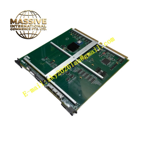
Description
Honeywell 51403519-160
Technical Specifications
- Video outputs: 1 DVI-D digital port, 1 analog RGB VGA port
- Supported resolution: 1920 x 1080 at 60 Hz
- Backplane interface: TPS operator station VME bus
- Supply power: 5 V DC from backplane
- Operating temperature: 0 °C to +60 °C
- Color depth: 24-bit true color
Functional Features Supports both digital DVI and analog RGB monitors, flexible for different display hardware. High resolution 1080p output, sharp rendering of process mimic diagrams. On-board LEDs indicate video output active and fault status. Automatic monitor detection, configures output timing to match connected monitor native resolution. Hot swap support, faulty board replacement without station reboot. Backward compatible with all TPS operator station main processor revisions.
Application Scenarios LCD monitor upgrade for legacy CRT-based TPS operator stations Spare part replacement for video output faults in operator stations Display hardware refresh during control room modernization Multi-monitor operator station setups
Performance Parameters
- Video output refresh rate: 60 Hz
- Output latency: ≤16 ms
- DVI signal max cable length: 5 meters
- RGB signal max cable length: 10 meters
- Mean time between failures: 400,000 hours
Material Composition FR4 high-speed PCB substrate Video scaler ASIC chip DVI transmitter chip RGB DAC circuit Gold-plated DVI and VGA connectors Metal shielded front panel
Structural Features Standard VME form factor board. Front panel houses DVI-D and VGA video connectors. LED shows video output active status. Equal-length differential traces for DVI high-speed signals. Metal shielded enclosure contains high-speed video radiation.
Working Principle The board receives display frame data from the station processor over the VME bus. The video scaler adjusts frame resolution to match the connected monitor native display mode. Digital frame data is sent to the DVI transmitter for output on the DVI port, and converted to analog RGB by the DAC for VGA port output. The monitor EDID read function queries connected monitor capabilities, automatically setting optimal output timing.
Installation Requirements Insert the board into the dedicated graphics slot in the operator station. Connect LCD monitor cable to the appropriate DVI or VGA port. Power on the station, confirm display output matches the monitor native resolution. Adjust display scaling in station software if required.
Usage Notes DVI cable length must not exceed 5 meters; longer runs cause digital signal dropouts. Never connect monitor cables while station power is on; this damages video output circuits. Screen flickering indicates loose cable connection; tighten connectors during maintenance. Never install non-compliant graphics firmware; mismatched firmware causes no video output.







