



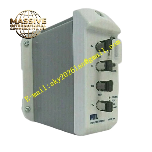
Description
Honeywell 8937-HN
Technical Specifications
- Brand: Honeywell / MTL
- Model: 8937-HN
- Product Type: Fibre optic extender module
- Power Supply: 20V to 30V DC
- Current Consumption: 85 mA to 74 mA maximum
- Ambient Temperature Range: -20°C to +70°C
- Hazardous Area Certification: Ex nA IIC T4 / Class I, Division 2, Groups A, B, C, D; T5 at Ta = 70°C
- Documentation Reference: MTL06ATEX8937X
- Installation Reference: MTL SCI-701, SCI-1012, SCI-1021
- Manufacturing Origin: Luton, England
- Mounting Method: Panel or system mounting, depending on installation design
Functional Features
- Extends PLC communication links over fibre optic cable.
- Provides electrical isolation between communication segments.
- Supports reliable data transmission in electrically noisy environments.
- Suitable for hazardous area installations when certified and installed correctly.
- Enables remote connection between PLC hosts and distributed I/O or communication nodes.
- Supports integration into Modicon PLC system architectures.
- Designed for industrial environments requiring stable long-distance communication.
Application Scenarios
- Modicon PLC system expansion.
- Factory automation and process control networks.
- Oil and gas facilities.
- Utility and power generation plants.
- Water and wastewater treatment systems.
- Transportation control systems.
- Building automation systems.
- Distributed I/O and remote communication applications.
Performance Parameters
- Power Supply: 20V to 30V DC
- Current Consumption: 85 mA to 74 mA maximum
- Ambient Temperature: -20°C to +70°C
- Hazardous Area Rating: Ex nA IIC T4 / T5 at 70°C
- Specific fibre optic connector type, maximum distance, data rate, channel count, IP rating, dimensions, and weight should be verified against the product nameplate and official MTL or Honeywell documentation.
Material Composition
- Industrial-grade printed circuit board
- Fibre optic communication interface
- Power supply circuitry
- Signal conditioning and isolation components
- Status indicator LEDs
- Metal or flame-retardant housing
- Model, revision, and serial number labels
Structural Characteristics
- Compact industrial module design.
- Provides fibre optic ports for communication extension.
- Includes power and communication connectors.
- Designed for installation in control rooms, cabinets, or compatible system enclosures.
- Typically includes status indicators for power and communication.
- Unconnected optical ports require protective dust caps.
- Exact connector layout and mechanical dimensions depend on the physical unit.
Working Principle
The 8937-HN converts electrical communication signals into optical signals for transmission over fibre optic cable. At the receiving end, optical signals are converted back into electrical signals for connection to PLC or communication equipment. This architecture extends communication distance, reduces electromagnetic interference, and improves system reliability in harsh industrial environments.
Installation Requirements
- Confirm compatibility with the target PLC or communication system.
- Verify the full model number 8937-HN.
- Check the nameplate for voltage, certification, and revision details.
- Follow plant electrical safety procedures.
- Supply power within the 20V to 30V DC range.
- Connect fibre optic cables only to compatible ports.
- Install protective dust caps on unconnected optical ports.
- Follow MTL installation documents SCI-701, SCI-1012, and SCI-1021 where applicable.
- After installation, check power and communication status indicators.
- Record the installation for maintenance traceability.
Precautions for Use
- Do not connect or disconnect the module in hazardous areas unless the area is confirmed non-hazardous or the approved live disconnection procedure is followed.
- Do not exceed the rated power supply voltage or current limits.
- Protect fibre optic connectors from contamination, dust, and mechanical damage.
- Store spare modules in a dry, clean, and static-safe environment.
- Do not use modules with damaged housings, damaged optical ports, or unclear labels.
- Perform functional checks after replacement.
- Refer to official MTL or Honeywell documentation for exact wiring, certification limits, and installation requirements.







