



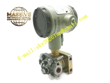
Description
Honeywell 900A16-0101
Technical Specifications
- Channel count: 16 digital output channels
- Output type: 24 V DC sink switch
- Rated per-channel current: 0.5 A
- Backplane interface: HC900 expansion serial bus
- Supply power: 24 V DC field supply
- Operating temperature: 0 °C to +60 °C
- Mounting: Standard 35 mm DIN rail
Functional Features Per-channel short-circuit protection, automatically limits current on overload. Per-channel LED indicates output ON state for each channel. Solid state switching, no mechanical contact wear for high-frequency operation. Configurable fail-safe output state on CPU stop. Hot swap support, module replacement without full system shutdown. Removable front terminal block speeds field wiring.
Application Scenarios Solenoid valve drive for small process skids HVAC damper actuator control Machine tool indicator light and alarm beacon drive Spare part replacement for failed digital output modules Packaging machine discrete output circuit integration
Performance Parameters
- Output response time: <20 μs
- Short circuit protection threshold: 0.6 A per channel
- Off-state leakage current: <0.1 mA
- Total module current rating: 8 A
- Mean time between failures: 450,000 hours
Material Composition ABS flame-retardant housing Power MOSFET output array Current sense resistors TVS protection diodes Removable screw terminal block Gold-plated backplane connector
Structural Features Narrow rectangular DIN-rail mount housing. Front removable terminal block for 16-channel output wiring. Side expansion bus connector mates to adjacent HC900 modules. Per-channel status LEDs aligned with terminal positions. Integral DIN rail locking clip.
Working Principle The HC900 CPU sends output commands over the expansion backplane bus. On-board logic drives the output transistor for the selected channel, pulling the field load circuit to ground and energizing the connected load. Current sense resistors monitor per-channel output current; overcurrent triggers automatic current limiting protection and channel fault flag. Per-channel LEDs illuminate to indicate active output state. On CPU stop, outputs revert to the pre-configured fail-safe state.
Installation Requirements Clip the module to the DIN rail adjacent to the CPU. Connect expansion bus cables between modules. Wire field loads to labeled output terminals. Install external fuses per output group at the field load distribution point. Test channel operation during commissioning, confirm short-circuit protection response.
Usage Notes Never exceed 0.5 A per-channel rated current, overload causes transistor overheating and failure. Install flyback diodes across inductive load terminals. Channel fault latch requires field short circuit resolution before software reset. Never connect AC line voltage to output terminals, high voltage destroys output transistors.







