



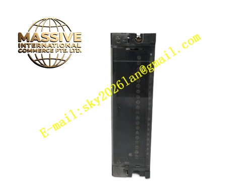
Description
Honeywell 900H02-0001
Technical Specifications
- Channel Quantity: 16 digital output channels
- Output Type: 24 VDC sourcing output
- Rated Output Voltage: 24 VDC
- Maximum Output Current per Channel: 0.5 A
- Working Temperature: 0°C to +60°C
- Storage Temperature: -40°C to +85°C
- Humidity Range: 5% to 90% RH non-condensing
- Isolation Rating: 500 VAC group to chassis isolation
- Power Consumption: 3.6 W maximum
- Rack Compatibility: HC900 standard I/O rack
- Certification: UL, C-UL, CE, FCC
Functional Features Each channel has independent short circuit current limiting protection. Single channel short circuit will not damage other channels. Each channel has status LED indicator to show output on/off state. It supports hot swap. It supports configurable fault safe state, including hold last state, force off, force on. It supports output loop diagnosis for overload and short circuit fault. It receives control instruction from controller via backplane bus. It supports logic configuration in Honeywell Process Control Designer.
Application Scenarios Solenoid valve control for fluid pipelines Indicator lamp and alarm beacon drive Auxiliary relay coil control for motor interlock Pump and fan on-off logic output Packaging machinery actuator control HC900 control system spare replacement
Performance Parameters
- Output Switching Response Time: less than 0.7ms
- Insulation Resistance: above 1000 MΩ
- Mean Time Between Failures: 870000 hours
- Overload Protection Trigger Threshold: 0.55 A
- EMC Electrostatic Discharge Immunity: 8kV contact discharge
Material Composition FR4 flame retardant printed circuit board Power MOSFET output drive chips Optocoupler isolation components Current sampling resistors TVS surge protection diodes ABS flame retardant front panel with printed channel number Tri-color LED indicators Metal rack locking buckle
Structural Features Standard HC900 plug-in module size. Front panel contains 16 channel LED indicators and power/fault indicator. Anti-misalignment notch on side to prevent wrong slot insertion. Rear gold finger contacts connect to rack backplane. Terminal wiring area is separated from electronic circuit zone. Lock clip fixes the module into rack slot firmly.
Working Principle Controller sends digital output command through backplane bus to the module on-board FPGA. FPGA sends drive signal to each channel MOSFET circuit. MOSFET turns on or off to output 24VDC signal to field load. Current sampling circuit monitors output current of each channel. When overload or short circuit occurs, current limiting circuit activates and reports fault information to controller.
Installation Requirements Cut off rack power before module insertion. Align notch and insert the module into empty slot, lock buckle. Connect field load wiring to corresponding channel terminals. Configure fault safe mode and output logic in configuration software. Power on the rack and test each channel on-off action. Separate signal wiring from high voltage power cable.
Usage Notes Each channel load current cannot exceed 0.5A maximum rating. Inductive load such as solenoid valve must add freewheeling diode at load side. Do not connect AC load directly to output terminals. Static protection must be taken during module replacement. Do not use this module in corrosive gas environment without sealed cabinet.







