Description
Honeywell CC-TCF901
Technical Specifications It supports installation of one CC-PCF901 module It carries 9 FTE 10/100Mbps Ethernet signal circuits Each network circuit includes ESD and surge protection components Operating temperature 0℃ to 60℃ Storage temperature -40℃ to 85℃ Humidity 5% to 95% non-condensing Backplane connector matches Series C rack bus Front RJ45 ports accept standard shielded FTE cables
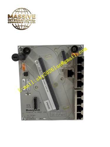
Functional Features It provides mechanical mounting platform and positioning for CC-PCF901 firewall switch module. It routes FTE Ethernet signals between the module and front panel RJ45 jacks. It integrates ESD protection and lightning surge suppression for each FTE port. It provides backplane power and diagnostic signal path for the installed CF9 module. Mechanical keying prevents fitting of incompatible module types.
Application Scenarios Cabinet-level FTE network termination base for petrochemical Experion PKS control cabinets Network termination for C300 controller rack CF9 firewall modules FTE signal distribution base for power plant control cabinet network security nodes Termination base for natural gas station control cabinet network isolation modules Network base for offshore platform control cabinet CF9 switch units
Performance Parameters Ethernet signal insertion loss meets 100BASE-TX specification Each port ESD protection meets IEC 61000-4-2 level 4 RJ45 contact cycle life exceeds 1000 insertions
Material Composition Base PCB uses FR4 flame retardant substrate with conformal coating RJ45 connectors have shielded metal shells ESD protection components are semiconductor transient suppressors Base housing is flame retardant gray PC plastic Backplane contacts are gold plated
Structural Characteristics Single-slot horizontal rack base Front panel equipped with nine shielded RJ45 FTE network ports Top surface has locating bosses and screw holes for fixing CC-PCF901 module Back connector plugs into Series C rack backplane Fool-proof protrusions prevent wrong module installation
Working Principle FTE network cables plug into the front RJ45 ports of CC-TCF901. Ethernet signals pass through surge protection circuits on the base PCB and reach the mating connector of CC-PCF901 module. The base distributes 24VDC rack power to the CF9 module and transfers module diagnostic status to the rack backplane bus. All network traffic processed by the firewall module passes through the signal paths integrated on this termination base.
Installation Requirements Install the base into Series C rack slot first, then secure CC-PCF901 module onto the base using specified torque screws Use Honeywell certified shielded FTE cables for all connections Maintain cabinet protective earth connection with grounding resistance ≤4Ω Do not route FTE cables alongside high voltage power cables
Usage Notes Do not use ordinary non-shielded Ethernet cables for FTE links connected to this base Keep the module fixing screw torque within the limit to avoid PCB damage Inspect port shielding continuity periodically This base cannot work independently without CC-PCF901 module installed