



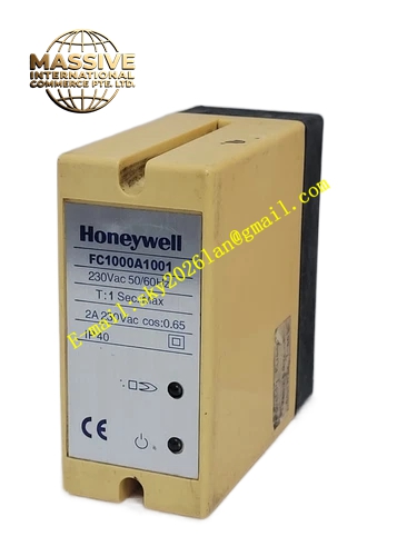
Description
Honeywell FC1000A1001
Technical Specifications
- Input Signal: UV photocell weak flame pulse signal
- Power Supply: 120VAC / 230VAC selectable, 50/60Hz
- Flame Response Time: 2s maximum flame loss response
- Relay Contact Rating: 250VAC, 3A resistive load
- Working Temperature: 0°C to +60°C
- Storage Temperature: -40°C to +85°C
- Relative Humidity: 5% to 90% RH non-condensing
- Mounting: DIN rail or panel mounting
- Certification: UL, C-UL, CE, FM
Functional Features It amplifies low amplitude UV flame signal from flame probe. It filters out interference signal from sunlight, welding arc and fluorescent lamp. It provides flame present and flame loss relay contact output. It detects probe open circuit, short circuit and module internal fault. It has adjustable flame sensitivity threshold. It provides LED indicator for flame detected, power and fault status. It supports lockout function when flame loss occurs during burner running. It provides manual reset interface after safety lockout.
Application Scenarios Industrial boiler UV flame detection amplifier Gas fired furnace burner flame safety control Oil heater combustion flame monitoring Refinery process heater flame detection Food and pharmaceutical drying oven burner control Combustion safety control system spare part
Performance Parameters
- Signal Amplification Gain: Adjustable from 50 to 1200 times
- Flame detection threshold: Continuously adjustable
- Relay Mechanical Life: 100000 operations at rated load
- Mean Time Between Failures: 970000 hours
- False Rejection Rate: Less than 0.1% for stable flame
Material Composition FR4 flame retardant PCB High gain operational amplifier chips Signal filter capacitor and resistor array UV signal comparator circuit Electromagnetic relay ABS flame retardant housing LED status indicators Metal mounting bracket and screw terminals
Structural Features Compact rectangular plastic housing. Front panel has sensitivity adjustment potentiometer and LED indicators. Rear side screw terminal block for UV probe wiring, power supply and relay output. Internal circuit separates weak signal input zone and power relay zone. Housing has mounting holes for panel installation or DIN rail clip for rail mounting.
Working Principle UV flame detector generates weak pulse current signal when flame ultraviolet radiation hits the photocell. The weak signal enters FC1000A1001 amplifier circuit. The amplifier filters noise and amplifies valid flame pulse signal. The comparator judges whether flame signal amplitude exceeds threshold. If flame signal exists, the flame relay energizes. If flame signal disappears continuously for preset time, the relay de-energizes and triggers burner safety lockout alarm.
Installation Requirements Mount module on control panel or DIN rail. Wire UV flame probe cable to signal input terminals. Connect AC power supply and burner safety interlock wiring to relay terminals. Adjust flame sensitivity potentiometer after burner commissioning. Power on system and test flame on and flame off action. Route flame probe cable separately from high voltage ignition cable.
Usage Notes UV probe cable must be shielded cable to reduce electromagnetic interference. Do not expose amplifier module to direct high temperature radiation from burner. Adjust sensitivity properly to avoid false flame signal. Replace relay component when contact ablation appears after long time operation. Do not connect high voltage ignition wire to signal input terminal.







