



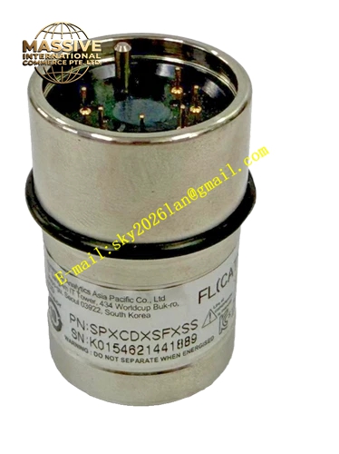
Description
Honeywell SPXCDXSHXSS
Technical Specifications
- Target Gas: Hydrogen Sulfide (H₂S)
- Measurement Range: 0 ppm to 100 ppm
- Resolution: 1 ppm
- Power Supply: 12 VDC to 32 VDC, nominal 24 VDC
- Communication Interface: RS485 Modbus RTU
- Analog Output: 3-wire 4-20mA sink or source configurable
- Relay Output: Three programmable relays for high alarm, low alarm and fault
- Operating Ambient Temperature: -40°C to +65°C
- Storage Temperature: -40°C to +75°C
- Relative Humidity: 10% to 95% RH non-condensing
- Protection Rating: IP66
- Cable Entry: Dual M20 threaded cable glands
- Certification: ATEX, IECEx, UL, CSA, INMETRO
- Sensor Type: Electrochemical Surecell sensor
Functional Features Tri-color backlit LCD display provides clear status indication with green for normal operation, yellow for fault warning and red for gas alarm. All calibration and parameter setup operations complete by magnetic wand without enclosure opening. It supports remote sensor mounting up to 30 meters away from transmitter main body. It continuously records sensor drift, circuit fault and flow abnormality data. It allows independent configuration of high alarm threshold, low alarm threshold and fault delay. It supports multi-drop Modbus wiring to reduce field cable quantity. It performs automatic sensor recognition after cartridge replacement. It locks alarm status until manual reset operation. It provides built-in overvoltage and reverse polarity protection.
Application Scenarios Sewage treatment plant hydrogen sulfide leak monitoring Oil and gas wellhead and pipeline station gas detection Refinery sulfur recovery unit toxic gas monitoring Chemical plant sulfur process workshop safety monitoring Wastewater lift station confined space fixed gas monitoring Marine offshore platform hazardous gas monitoring
Performance Parameters
- Measurement Accuracy: ±5% of full scale reading
- T90 Response Time: Less than 30 seconds
- Long Term Drift: Less than 5% of full scale within twelve months
- Sensor Service Life: 36 months under normal operating environment
- Relay Contact Rating: 5A at 250VAC resistive load
- Maximum Loop Resistance: 600 ohm at 24VDC supply
- Mean Time Between Failures: 740000 hours
Material Composition LM25 flameproof cast aluminum alloy enclosure Electrochemical hydrogen sulfide sensing cell SMT main control and signal conditioning PCB Tri-color backlit LCD display module Epoxy coated circuit board for anti-corrosion PTFE hydrophobic dust filter membrane Fluorine rubber sealing O-rings Brass cable gland fittings Polycarbonate display window
Structural Features Flameproof split housing structure with electronics compartment and sensor compartment. The front display module can be detached to access internal screw terminal blocks. Internal wiring terminals adopt pluggable socket design for convenient pre-wiring. Built-in integrated mounting bracket supports wall surface installation or pipe mounting. Anti-tamper locking screw prevents unauthorized opening of explosion-proof housing. Independent flow channel guides sample gas to sensing cell. Internal isolation barrier separates power circuit and low level sensor signal circuit.
Working Principle Hydrogen sulfide gas diffuses through the inlet filter membrane into electrochemical sensor cavity. Target gas reacts on working electrode and generates weak current signal proportional to gas concentration. Signal conditioning circuit amplifies raw signal and applies temperature compensation. Microcontroller converts analog signal into digital concentration value and drives LCD display. The unit outputs 4-20mA analog signal and Modbus data to DCS or gas controller. When concentration exceeds preset threshold, internal relay activates external alarm devices. Built-in diagnostic circuit monitors sensor aging and circuit failure state.
Installation Requirements Select mounting position according to gas density; hydrogen sulfide is heavier than air so install detector at low elevation near potential leakage points. Fix the integrated mounting bracket firmly on wall or pipe surface. Route shielded twisted pair cable through M20 cable gland and terminate wires to internal terminals. Complete earth connection with low impedance grounding wire. Set alarm threshold and Modbus address via magnetic wand after power on. Perform zero calibration in clean fresh air and span calibration with certified H₂S standard gas. Tighten all sealing screws and cable gland to maintain IP66 and flameproof integrity.
Usage Notes Do not expose the detector to high concentration organic solvent vapor which causes irreversible sensor poisoning. Replace sensor cartridge immediately after reaching service life. Conduct span calibration every six months with certified calibration gas. Keep gas inlet filter clean and remove dust accumulation regularly with dry soft brush. Do not open the flameproof housing in hazardous explosive atmosphere. Verify relay action and communication signal after each calibration.







