



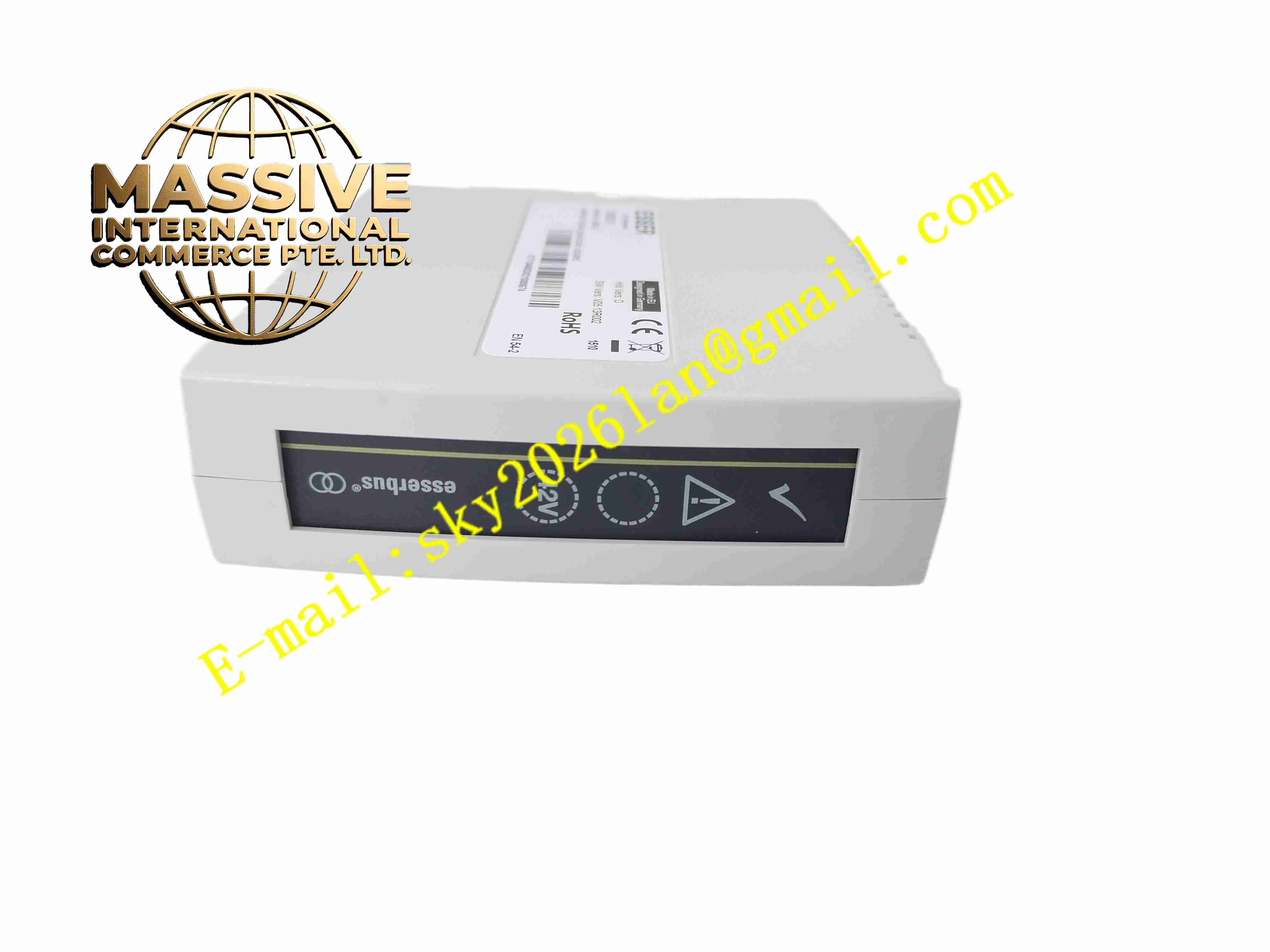
Description
Honeywell FX808331
Technical Specifications
- Product Type: Transmitter main circuit board assembly
- Input Signal: Sensor bridge millivolt signal
- Output Signal: 4-20mA with HART digital superimposed signal
- Power Supply: 12 to 42 V DC loop powered
- Communication Protocol: HART 5 / HART 7
- Accuracy: ±0.1% of full scale
- Protection Rating: Board assembly IP00, installed inside transmitter housing IP67
- Operating Temperature: -40 °C to +85 °C
- Mounting Method: Internal installation inside field transmitter housing
Functional Features
- Raw sensor bridge signal amplification and temperature drift compensation.
- High precision analog to digital conversion for process variable measurement.
- 4-20mA current output proportional to measured process value.
- HART digital communication supports parameter configuration and diagnostic readback.
- Built-in sensor fault detection identifies sensor open or short circuit.
- Digital damping function stabilizes output signal for noisy process measurement.
- Non-volatile memory stores calibration data, tag number and range setting.
- Overvoltage and reverse polarity protection protects circuit from loop wiring fault.
- Self-diagnostic function reports electronic fault to HART communicator.
- Conformal coated PCB withstands high humidity and corrosive atmosphere inside transmitter housing.
Application Scenarios
- Petrochemical plant pressure transmitter electronic replacement
- Refinery temperature transmitter spare electronics assembly
- Offshore platform process instrument repair spare board
- Chemical plant level transmitter electronic component replacement
- Power plant boiler process transmitter maintenance spare part
Material Composition
- Main PCB: FR4 printed circuit board with conformal coating
- Signal processing chips: Instrumentation amplifier and microcontroller
- Memory components: Non-volatile EEPROM memory chip
- HART modem chip: HART communication integrated circuit
- Passive components: Precision metal film resistors and capacitors
- Protection components: Surge suppression diodes and current limit resistors
Structural Characteristics
- Compact rectangular PCB board designed to fit inside transmitter enclosure.
- Edge connectors for sensor bridge wiring and loop power connection.
- Surface mount components densely arranged on PCB.
- Internal circuit layout separates low level sensor signal circuit and HART communication circuit.
- Conformal coating fully covers PCB surface to resist moisture and chemical vapor.
- Small form factor matches mechanical dimension of Honeywell transmitter housing.
Working Principle Sensor bridge produces millivolt signal proportional to process variable. FX808331 amplifies and compensates raw sensor signal, converts analog value to digital reading. Onboard microcontroller calculates calibrated process value and controls 4-20mA loop current. HART modem superimposes digital communication signal onto analog current loop. HART communicator can read tag, range and diagnostic information and write configuration parameters into board memory. When sensor fault occurs, board sets output to specified fault current level.
Installation Requirements
- Install board inside matched Honeywell transmitter housing.
- Connect sensor bridge terminals and loop power terminals according to marking.
- Torque transmitter housing screws to specified value to maintain sealing integrity.
- Perform full calibration and range setting after board replacement.
- Verify HART communication connection and fault alarm function.
- Test 4-20mA output signal across full measurement range.
Usage Notes
- Use anti-static wristband during board handling and replacement.
- Do not touch conformal coated circuit area with bare fingers.
- Re-calibrate transmitter every time after replacing FX808331 board.
- Do not apply voltage exceeding 42V DC to loop terminals.
- Verify housing gasket integrity to prevent moisture ingress after installation.
- Keep spare board stored in anti-static packaging.
- Replace board immediately when permanent electronic damage occurs.







