



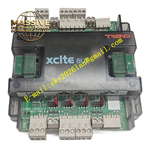
Description
Honeywell IQ3XCITE-IO-8UI
Technical Specifications
- Channel Quantity: 8 independent universal input channels
- Supported Signal Type: NTC10K thermistor, 0-10VDC, 0-20mA, 0-5VDC, resistance signal
- Analog Resolution: 12 bit
- Communication Interface: XCITE dedicated I/O bus
- Working Ambient Temperature: 0°C to +60°C
- Storage Temperature: -40°C to +85°C
- Relative Humidity: 5% to 90% RH non-condensing
- Isolation Rating: 500VAC channel to logic isolation
- Mounting Method: TS35 DIN rail mounting
- Certification: UL60730, CE, RoHS
Functional Features Each channel supports software switching among multiple sensor signal modes. It provides high precision sampling and signal filtering for analog input. It uploads real-time measured value and channel fault diagnostic information to host controller. It has dedicated LED indicator for power, module fault and each channel status. It adopts two-part removable terminal connector for convenient wiring and maintenance. It supports cascading on XCITE I/O bus together with other XCITE I/O modules. It detects open circuit and short circuit fault of sensor wiring loop. It supports sensor value scaling and alarm threshold configuration inside the module.
Application Scenarios Duct temperature and NTC temperature sensor signal monitoring Air handling unit supply and return water temperature collection Room temperature and humidity analog transmitter signal acquisition Differential pressure transmitter signal for air filter monitoring Chilled water flow and pressure sensor signal collection Building automation universal analog monitoring spare module
Performance Parameters
- Measurement Accuracy: ±0.3°C for NTC10K within -20°C to +90°C
- Analog Signal Accuracy: ±0.5% of full scale
- Insulation Resistance: Greater than 1000 MΩ
- Mean Time Between Failures: 930000 hours
- EMC Surge Withstand: 1kV line to earth
- Terminal Wiring Specification: 0.5mm² to 2.5mm² copper wire
Material Composition FR4 flame retardant PCB substrate 12-bit analog to digital conversion chip Precision signal conditioning operational amplifier TVS surge suppression diodes Metal film reference resistors Nylon UL94 V-0 removable terminal block ABS flame retardant housing Tri-color LED status indicators Steel DIN rail elastic locking clip
Structural Features DIN rail compact rectangular housing structure. Front panel carries removable terminal plug and channel LED indicators. Rear side XCITE bus connector for interconnection with host or other I/O modules. Internal PCB layout separates analog signal sampling zone and digital communication zone to reduce crosstalk. Quick-release locking clip fixes the module on DIN rail. Anti-key notch prevents reverse bus connection. Transparent label area marks channel number and signal type.
Working Principle Field sensor signal enters the universal input channel terminal. The signal conditioning circuit converts different types of sensor signal into standard voltage signal. ADC chip converts analog signal into digital value. On-board logic chip filters noise and transmits digital measurement data to IQ3XCITE host controller via XCITE I/O bus. When sensor wire is open or shorted, the module identifies fault state and sends fault alarm message to host.
Installation Requirements Mount IQ3XCITE-IO-8UI on TS35 DIN rail inside indoor control cabinet. Wire sensor shielded twisted pair cable to the corresponding channel terminal. Connect XCITE I/O bus cable between module and host controller. Set sensor type, scaling parameter and alarm threshold in IQ3 engineering software. Power on the bus and verify measured value matches field instrument reading. Separate analog signal cable from inverter and high frequency power cable.
Usage Notes Each channel must be configured to match the actual connected sensor type. Shielded twisted pair cable is mandatory for 4-20mA and 0-10V analog signal wiring. Do not apply voltage exceeding 30VDC to input terminals. Keep the cabinet internal temperature stable to avoid measurement drift. Do not install this module in corrosive gas environment.







