



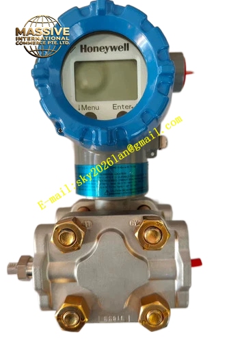
Description
Honeywell STD725-E1AC4AS-1-G-AHS-11C-A-00A0-00-0000
Technical Specifications
- Measurement Type: Differential Pressure
- Communication Protocol: HART 7
- Output Signal: 4-20mA two-wire analog plus HART digital
- Turndown Ratio: 100:1
- Supply Voltage: 10.8 VDC to 42.4 VDC
- Operating Ambient Temperature: -40°C to +85°C
- Process Medium Temperature: -40°C to +125°C
- Relative Humidity: 0% to 100% RH non-condensing
- Protection Rating: IP66 / IP67, Type 4X
- Process Connection: 1/2 inch NPT female
- Electrical Entry: 1/2 inch NPT threaded port
- Certification: SIL2, FM, CSA, ATEX, IECEx
- Wetted Material: 316L stainless steel
Functional Features On-chip automatic static pressure and temperature compensation eliminates measurement drift caused by medium temperature and line pressure fluctuation. Local LCD display supports four configurable display pages and 0/90/180/270 degree rotation. Three local push buttons complete range setting, zero trim and device reset without handheld communicator. It supports multi-variable transmission including differential pressure, static pressure and sensor temperature via HART. It provides comprehensive self-diagnosis including sensor fault, over-range, electronics failure and wiring fault. It supports remote configuration and trending recording through HART host. It retains configuration data permanently after power loss. It supports device tag and descriptor storage for field identification. It provides configurable fail-safe output mode.
Application Scenarios Orifice plate and venturi tube flow measurement for liquid, gas and steam Tank liquid level measurement by differential pressure method Heat exchanger pressure drop monitoring Filter and pipeline pressure differential monitoring Boiler and furnace draft pressure measurement Petrochemical reactor differential pressure monitoring
Performance Parameters
- Reference Accuracy: ±0.05% of calibrated span
- Long Term Stability: ±0.02% of full span over ten years
- Response Time: 80ms minimum configurable
- Insulation Resistance: Greater than 1000 MΩ
- Load Resistance: Maximum 1100 ohm at 24VDC supply
- Mean Time Between Failures: 950000 hours
- Temperature Effect: Less than 0.015% URL per °C
Material Composition 316L stainless steel wetted pressure sensor diaphragm Low copper aluminum alloy transmitter housing with polyester powder coating Silicone sealing O-ring for electronics compartment FR4 multilayer conformal coated PCB Piezoresistive sensing chip HART communication modem chip Backlit LCD display assembly Zinc plated carbon steel mounting bracket
Structural Features Dual compartment housing design separates electronics chamber and pressure sensing chamber to protect circuit from process medium heat and corrosion. The display module can be rotated freely at four angles for convenient reading. Isolated pressure sensing module with two independent high pressure and low pressure process ports. Removable terminal block simplifies wiring work. Pipe mounting bracket supports 2-inch standard pipe installation. Internal pressure channel is polished to avoid medium residue accumulation. Anti-tamper locking structure prevents unauthorized parameter modification.
Working Principle Process medium pressure is transmitted to high side and low side of piezoresistive sensor diaphragm. The diaphragm deforms under differential pressure and changes resistance value of integrated strain gauge array. Sensing chip converts resistance variation into weak electrical signal. On-board ASIC circuit applies static pressure and temperature compensation and converts signal into standard 4-20mA analog value. Digital HART modulation signal is superimposed on 4-20mA loop for remote communication. Microcontroller uploads diagnostic status and measurement variables to host system. When pressure exceeds measuring range, the unit triggers over-range alarm and sets output to pre-configured fail value.
Installation Requirements Select proper installation position to avoid liquid condensate accumulation in impulse pipe for gas measurement and avoid gas bubble for liquid measurement. Mount transmitter on 2-inch pipe or vertical wall with supplied bracket. Connect high side and low side impulse piping to corresponding process ports. Route shielded two-wire cable through electrical entry and terminate to internal terminals. Complete reliable instrument grounding. Perform zero trim after impulse piping filling and pressure stabilization. Set measurement range, unit and fail-safe mode via local buttons or HART communicator. Verify output value consistency with reference pressure gauge.
Usage Notes Do not apply pressure exceeding upper range limit to sensing diaphragm. Isolate the transmitter and release internal pressure before removing impulse piping. Avoid mechanical impact and vibration on sensor module. Use compatible sealing gasket material matching process medium. Conduct regular zero trim according to site calibration cycle. Do not open electronics compartment in hazardous classified area unless power is isolated and site permit is obtained.







