



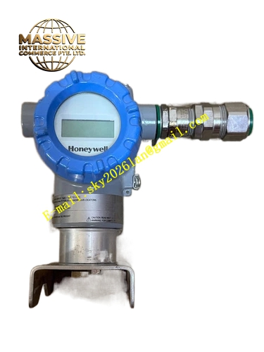
Description
Honeywell STT850-S-0-G-AHB-11S-A-00A0-00-0000
Technical Specifications
- Sensor Input Type: Pt100, Pt1000, Cu50, J, K, T, E, R, S, B, N thermocouple
- Channel Quantity: Single input
- Communication Protocol: HART 7
- Output Signal: 4-20mA two-wire analog plus HART digital
- Supply Voltage: 11.8 VDC to 42.4 VDC
- Operating Ambient Temperature: -40°C to +85°C
- Relative Humidity: 0% to 100% RH non-condensing
- Protection Rating: IP66 / IP67, Type 4X
- Electrical Entry: 1/2 inch NPT threaded port
- Certification: SIL2/SIL3, FM, CSA, ATEX, IECEx
- Update Time: 125ms for single channel
Functional Features Sensor matching function compensates inherent sensor error to reduce total loop measurement error. Local LCD display supports four adjustable screen pages and 4-angle rotation. Three local push buttons realize range setting, sensor type selection and zero adjustment. It detects sensor open circuit, short circuit and sensor drift trend. It supports temperature unit switching between Celsius, Fahrenheit, Kelvin and raw resistance/millivolt display. It stores sensor calibration data and device tag information. It supports remote configuration, trending and fault reading via HART communicator or DCS workstation. It provides configurable fail-safe output value for sensor fault condition. It supports average, difference and redundant temperature calculation for dual input variant.
Application Scenarios Petrochemical reactor and pipeline temperature monitoring Power plant boiler and steam pipe temperature measurement Pharmaceutical batch reactor temperature control loop Natural gas compression station temperature monitoring Refinery furnace tube skin temperature measurement Food and beverage sterilization process temperature control
Performance Parameters
- Digital Accuracy for RTD: ±0.1°C
- Long Term Stability: ±0.01% of URL per year for ten years
- Insulation Resistance: Greater than 1000 MΩ
- Load Resistance: Maximum 1100 ohm at 24VDC supply
- Mean Time Between Failures: 920000 hours
- EMC Immunity: Compliant with IEC 61000 series industrial standard
Material Composition Low copper aluminum alloy transmitter housing with polyester powder coating Silicone sealing O-ring for dual compartment FR4 conformal coated PCB signal processing board High precision ADC conversion chip HART communication modem Backlit rotatable LCD display module Zinc plated carbon steel mounting bracket 316 stainless steel optional housing for corrosive environment
Structural Features Dual compartment isolation structure separates sensing signal terminal chamber and electronic circuit chamber. Display module can be detached and rotated freely without opening main electronics compartment. Removable spring terminal block simplifies field wiring. Standard 2-inch pipe mounting bracket fits common industrial installation. Internal circuit layout isolates low level thermocouple millivolt signal from power circuit to reduce noise interference. Anti-rotation locking structure prevents accidental parameter modification.
Working Principle RTD resistance signal or thermocouple millivolt signal enters transmitter input terminal. Precision signal conditioning circuit amplifies weak raw signal and applies cold junction compensation for thermocouple input. ADC converts analog signal into digital temperature value. Microcontroller calculates temperature result and drives LCD display. Standard 4-20mA analog output is generated according to configured range. HART modem superimposes digital data on analog loop to transmit temperature value, sensor health and diagnostic information to host system. When sensor fault is detected, transmitter switches output to pre-defined fail level.
Installation Requirements Mount transmitter on 2-inch pipe or vertical wall with supplied bracket. Run shielded twisted pair sensor cable from temperature probe to transmitter terminals. Use dedicated thermocouple extension wire for thermocouple sensor connection. Route two-wire HART signal cable to control system and complete instrument grounding. Select sensor type, measurement range and fail-safe mode via local button or HART communicator. Verify temperature reading consistency with local reference thermometer. Separate sensor signal cable from high voltage AC power cable in wiring duct.
Usage Notes Do not use ordinary copper wire to replace thermocouple extension wire. Avoid strong electromagnetic field and vibration near installation location. Replace sensor probe immediately if open circuit or short circuit fault appears. Conduct regular calibration according to site safety instrument system cycle. Do not open electronics compartment in hazardous area without hot work permit. Check terminal screw tightness periodically to avoid poor contact under vibration.







