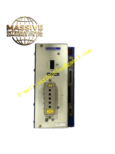
Description
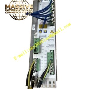
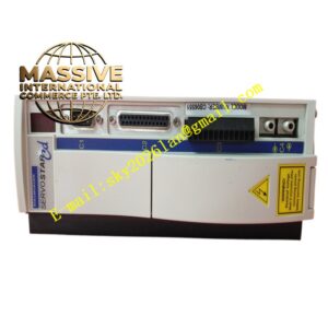
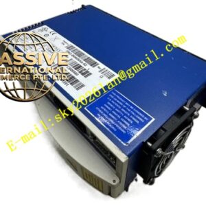
Kollmorgen SR55200-000000
Technical Specifications
| Parameter Category | Specific Specification |
|---|---|
| Manufacturer | Kollmorgen (Danaher Motion) |
| Product Family | SERVOSTAR S200 Series |
| Power Supply | 3-Phase, 230 VAC nominal |
| Input Current | 65 Amps per phase |
| Input Power | 26 kVA |
| Output Voltage | 3 x 230 VAC (variable frequency) |
| Output Current | 55.0 Amps RMS continuous per phase |
| Peak Output Current | 110.0 Amps RMS (2 seconds) |
| Output Power | 22 kVA continuous |
| PWM Frequency | 8 kHz |
| Control Modes | Torque, velocity, position |
| Command Interface | ±10V analog, step/direction, encoder following |
| Feedback | Resolver, incremental encoder, SFD, absolute encoder |
| I/O | 4 digital inputs, 3 digital outputs, 2 analog outputs |
| Protection | Overcurrent, overvoltage, undervoltage, overtemperature, phase loss, ground fault, stall detection |
| Operating Temperature | 0°C to +40°C |
| Storage Temperature | -25°C to +55°C |
| Protection Class | IP20 |
Key Features
- Very High Current Capacity: 55A continuous output with 2:1 peak capability drives large servo motors up to approximately 15 kW at 230 VAC
- Heavy-Duty Construction: Substantial power stage and thermal design for reliable continuous operation in industrial environments
- Multiple High-Resolution Feedback Options: Supports all major feedback technologies including absolute encoders for applications requiring position retention
- Expanded Analog I/O: Dual analog outputs enable monitoring of actual velocity, torque, or following error for diagnostic and control purposes
- Advanced Stall Detection: Monitors motor current and velocity to detect mechanical stalls, protecting both drive and mechanical system
- Regeneration Management: Sophisticated regeneration monitoring with automatic braking resistor engagement protects DC bus from overvoltage
Application Scenarios
- Large CNC machining centers: Drives axis motors in gantry mills, large vertical machining centers, and multi-axis turning centers
- Heavy industrial robots: Powers large payload articulated robots, gantry robots, and portal robots in automotive and heavy manufacturing
- Metal extrusion and forging: Controls hydraulic replacement servo drives in extrusion presses and forging hammers
- Large injection molding: Drives clamp and injection units in large-tonnage all-electric injection molding machines
- Steel mill equipment: Controls roll positioning, strip guiding, and tensioning in hot and cold rolling mills
- Large test stands: Powers engine dynamometers, structural test rigs, and fatigue test machines
- Mining equipment: Drives conveyor systems, hoist mechanisms, and positioning equipment in harsh environments
Performance Parameters The drive maintains the S200 series 800 Hz speed loop bandwidth while handling significantly higher power levels. The current loop bandwidth is 3-5 kHz with smooth torque delivery. The 8 kHz PWM frequency is maintained to ensure smooth torque delivery. Position loop update rate is 500 microseconds with 32-bit resolution. The drive supports advanced features including inertia estimation, vibration suppression, and adaptive gain tuning. Current regulation accuracy is within 1% of commanded value across the full operating range.
Material Composition The drive features a very substantial steel enclosure with heavy-duty textured powder coating for industrial durability. Power semiconductors are high-current IGBT modules mounted on direct-bonded copper (DBC) substrates with excellent thermal and electrical properties. The DC bus employs multiple large-can electrolytic capacitors in parallel for high ripple current capacity. The control board uses an 8-layer PCB with extensive copper planes for current carrying and noise immunity. Internal bus bars are copper with tin plating for high-current distribution. The heat sink is a massive extruded aluminum assembly with integral cooling fan and ducting.
Structural Characteristics The drive is the largest in the S200 series, with a substantial footprint and weight reflecting the 55A power capability. Power terminals are high-capacity barrier-type blocks accepting wire up to 35 mm². Control connectors are heavy-duty pluggable blocks with screw clamps. The front panel includes a comprehensive display showing current, voltage, speed, and fault information, plus multiple status LEDs. Dual cooling fans provide redundant airflow through the large heat sink assembly. The enclosure includes lifting handles for installation. Internal layout features separate power and control compartments with substantial EMI shielding.
Working Principle The drive operates on the same fundamental vector control principles as other S200 series drives, scaled for very high current. Three-phase 230 VAC input is rectified to 325 VDC bus voltage. The high-capacity IGBT inverter generates variable-frequency output capable of delivering 55A continuous current. The DSP-based control system implements field-oriented control with advanced algorithms for high-power motor control. Multiple current sensors provide precise phase current feedback. The drive includes sophisticated thermal modeling to predict semiconductor junction temperatures and prevent thermal damage. Regeneration energy is monitored and diverted to external braking resistors when bus voltage rises.
Installation Requirements
- Mount on a substantial panel or floor-standing enclosure capable of supporting the drive weight
- Provide minimum 200 mm clearance on all sides; 300 mm above for fan exhaust
- Connect three-phase power through molded case circuit breaker rated for 80A with D-curve trip
- Install external AC line reactor (3% impedance minimum) rated for 80A continuous
- Use motor power cables of 25 mm² minimum cross-section with proper lugs
- Connect resolver or encoder feedback using heavy-duty shielded cable
- Install external braking resistor rated for the application’s regenerative energy
- Provide separate control power supply (24 VDC) for logic circuits if required
- Separate power and control cables by minimum 500 mm
- Commission drive using comprehensive auto-tuning sequence due to high power levels
Usage Precautions
- Verify all power connections with torque wrench; loose connections at 55A cause severe arcing
- Do not energize drive without proper cooling airflow; thermal damage occurs within minutes
- Monitor DC bus voltage continuously during operation; overvoltage causes immediate shutdown
- Check braking resistor temperature if regeneration is frequent; resistor failure causes overvoltage fault
- Inspect power terminals monthly for signs of overheating or corrosion
- Replace cooling fans proactively; dual fan design provides redundancy but both should be functional
- Do not attempt to repair internal power stage; high voltage and current create lethal hazards
- Store spare drive in climate-controlled environment; large capacitors have finite shelf life
- Follow comprehensive lockout/tagout procedures; DC bus energy is substantial and hazardous
- Use only qualified personnel for installation and maintenance due to high power levels