



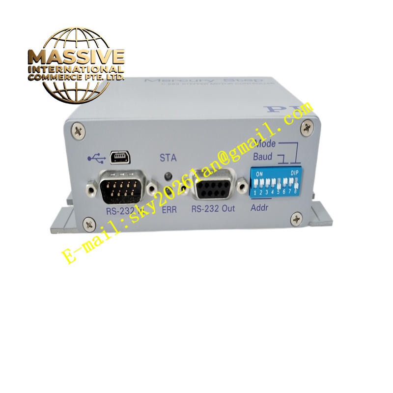
Description
MERCURY STEP C-663
Technical Specifications Two-phase bipolar stepper motor drive; microstep resolution configurable through DIP switches; 24V DC to 48V DC main power supply; maximum selectable phase current; pulse and direction control signal interface; opto-isolated command input circuits; operating temperature 0°C to +50°C; IP20 protection rating.
Functional Features Accept pulse and direction digital signals from PLC or motion controllers. Convert pulse command signals into sequenced phase current excitation for two-phase stepper motors. Support microstep subdivision selection to improve positioning smoothness and reduce motor resonance. Provide enable signal input to activate or deactivate motor current. Monitor internal power stage temperature and trigger over-temperature protection. Maintain holding current at reduced level when motor stops to reduce heat generation.
Application Scenarios Small automated stage positioning, labeling machine adjustment axes, 3D auxiliary motion equipment, laboratory sample translation stages, low-speed material positioning mechanisms.
Performance Parameters Adjustable microstep resolution; reduced resonance with microstep operation; stable holding torque at standstill; simple pulse-direction command compatibility with mainstream controllers.
Material Composition Main drive PCB uses FR-4 flame-retardant multilayer substrate; power drive components are MOSFET semiconductor switches; optocoupler chips isolate pulse and direction input signals; heat sink is aluminum alloy; housing is flame-retardant plastic; terminal blocks use nickel-plated copper contacts.
Structural Characteristics Compact rectangular DIN rail mount housing. Front panel has DIP switches for microstep and current setting plus status LED indicators. Screw terminal blocks on the top and bottom edges for power supply, motor winding and control signal wiring. Internal power stage mounted on aluminum heat sink for thermal dissipation.
Working Principle Pulse and direction commands pass through opto-isolation circuits to the onboard logic chip. The logic chip generates phase excitation sequence according to configured microstep setting. The MOSFET power stage switches current between motor windings in sequence. The sequential magnetic field rotation pulls the stepper motor rotor to advance one microstep per received pulse. The controller reduces winding current when no movement command exists to lower thermal load.
Installation Requirements Mount the drive controller on standard DIN rail. Wire DC power supply and stepper motor phase windings to motor terminals. Connect pulse, direction and enable control signals to command input terminals. Set phase current and microstep resolution using front DIP switches. Test motor jog motion and positioning response after power-on.
Precautions for Use Do not set phase current higher than the motor rated specification. Use twisted-pair motor wiring and keep signal cables away from high-power wiring. Allow cooling space around the heat sink. Disconnect DC power supply before adjusting DIP switch settings.







