Description
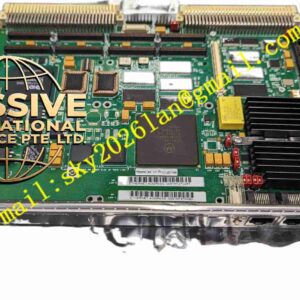
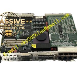
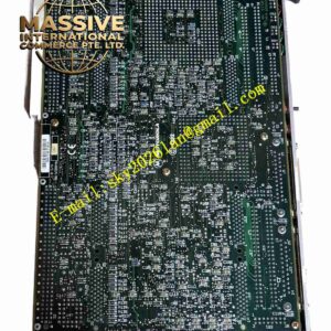
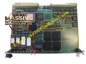
Motorola MVME257B
Technical Specifications
- Microprocessor: PowerPC 603e 32-bit RISC microprocessor.
- Clock Speed: 200 MHz.
- Memory: 32 MB or 64 MB ECC/Non-ECC DRAM.
- Non-Volatile Storage: 2 MB onboard Flash memory.
Functional Features
- Low Power Architecture: The 603e core provides high performance while maintaining minimal thermal output.
- Full VMEbus Compliance: Supports A32/A24/A16 addressing and D32/D16/D8 data transfers as both master and slave.
- Integrated Connectivity: Features 10/100Base-T Ethernet, dual RS-232 serial ports, and a SCSI-2 interface.
- System Management: Includes a hardware watchdog timer, Real-Time Clock (RTC), and NVRAM.
Application Scenarios
Widely deployed in telecommunications switching, industrial automation, data acquisition, medical instrumentation, and aerospace test equipment.
Performance Parameters
- Bus Throughput: Supports up to 40 MB/s VMEbus data transfer rate.
- Network: 10/100 Mbps adaptive Ethernet with full-duplex capability.
- Serial Communication: Supports baud rates up to 115.2 Kbps.
Material Composition
Manufactured using UL94V-0 flame-retardant multi-layer industrial-grade PCBs, featuring high-reliability BGA-packaged processors and vibration-resistant solder joints.
Structural Characteristics
Standard single-slot 6U VME form factor. The front panel integrates RJ45 network ports, DB9 serial connectors, status indicator LEDs, and a reset button.
Working Principle
Upon power-up, the PowerPC 603e processor loads the bootloader from Flash, initializes the hardware, and boots the Real-Time Operating System (RTOS). A PCI-to-VME bridge chip manages local peripherals and facilitates high-speed data exchange with the VME backplane.
Installation Requirements
Must be inserted into a standard 6U VME chassis backplane. Ensure P1 and P2 connectors are perfectly aligned and securely locked. The system must provide stable +5V and ±12V DC power.
Usage Precautions
Never hot-swap the module while powered. Always wear an ESD wrist strap during handling. Avoid operation in high-EMI environments without proper chassis shielding.