Description
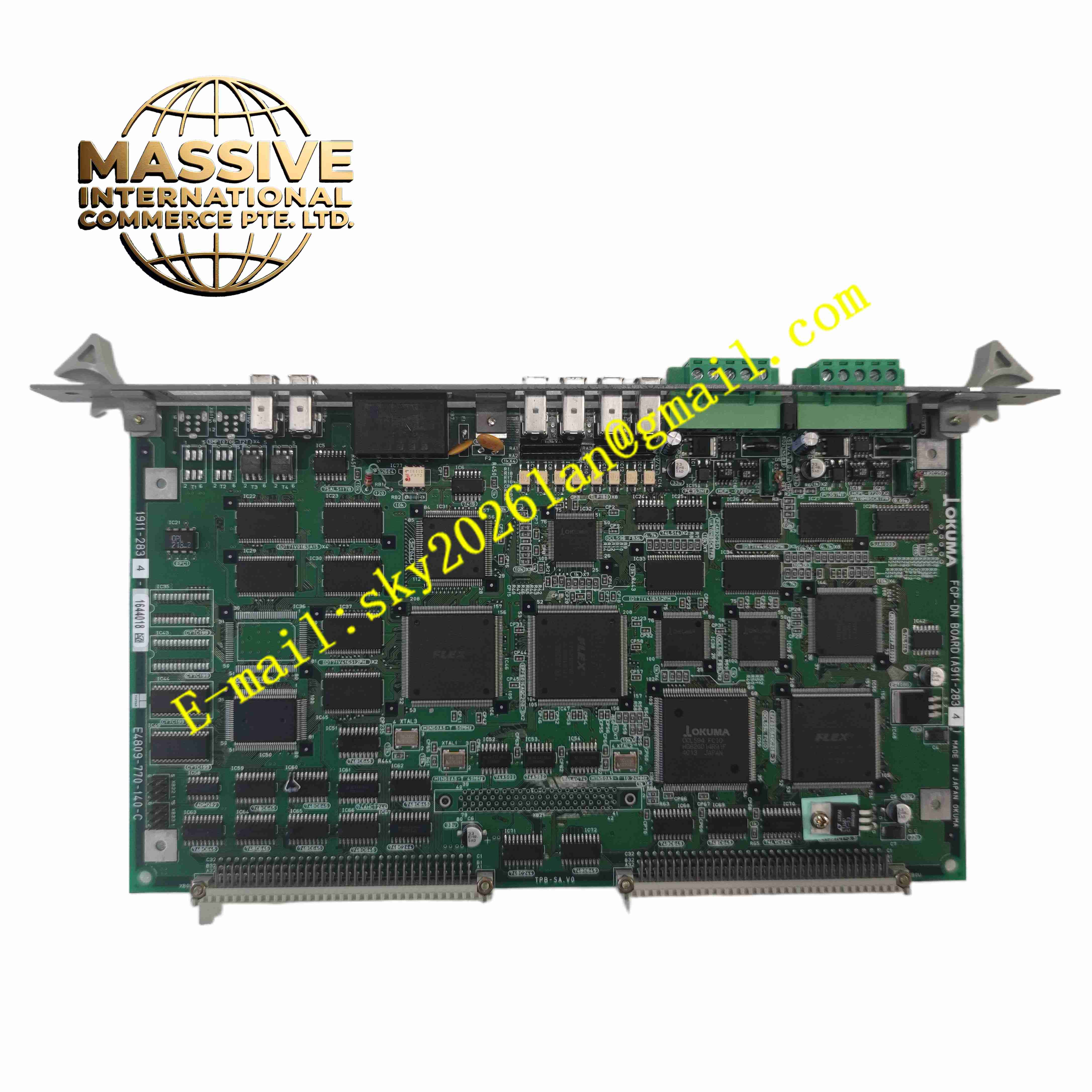
OKUMA FCP-DN A911-2834
Technical Specifications
- Product Type: DeviceNet communication interface board
- Model Code: A911-2834
- Bus Protocol: DeviceNet
- Communication Rate: 125 kbps, 250 kbps, 500 kbps adjustable
- Power Supply: 24 VDC bus power
- Interface Connector: DeviceNet terminal connector
- Protection Rating: IP00 for board installation inside CNC control cabinet
- Operating Temperature: 0 °C to +55 °C
- Mounting Method: CNC rack board slot mounting
Functional Features
- DeviceNet fieldbus interface realizes communication between Okuma CNC controller and DeviceNet field devices.
- Supports standard DeviceNet master or slave communication mode according to configuration.
- Transmits CNC motion control commands, machine tool status and alarm data over fieldbus.
- Receives sensor signal and remote I/O status data from field DeviceNet stations.
- Built-in bus error detection and communication fault diagnosis function.
- LED indicators display board power, bus activity and communication fault status.
- Galvanic isolation between CNC internal bus and DeviceNet fieldbus.
- Supports multi-drop bus topology for multiple field node connection.
- Overvoltage and overcurrent protection for DeviceNet bus port.
- Compatible with Okuma OSP series CNC machine control system.
Application Scenarios
- Okuma CNC machine tool DeviceNet remote I/O communication
- Automated machining production line fieldbus data exchange
- CNC lathe and machining center peripheral device control
- Factory automation machine tool sensor and actuator network
- Metal cutting workshop distributed machine control system
Material Composition
- Main PCB: FR4 printed circuit board
- Communication chip: DeviceNet protocol controller IC
- Transceiver: CAN bus transceiver chip
- Isolation components: High speed optocoupler isolation chips
- Backplane connector: Gold-plated copper contact pins
- Bus terminal block: Copper alloy screw terminals for DeviceNet cable
Structural Characteristics
- Standard CNC rack plug-in circuit board structure.
- Front panel fitted with LED indicators and DeviceNet bus terminal block.
- Rear gold-plated edge connector plugs into Okuma CNC internal backplane.
- Internal isolation barrier separates CNC control circuit and DeviceNet fieldbus circuit.
- Surface mount components are arranged on PCB to reduce electromagnetic interference.
Working Principle The board communicates with Okuma CNC main controller via internal rack backplane bus. It packages CNC control data into standard DeviceNet CAN frames and transmits data to fieldbus nodes. Received data from DeviceNet field devices is parsed and transferred to CNC controller. The board continuously monitors bus signal quality. When bus short circuit, cable break or communication error occurs, fault LED activates and fault information is sent to CNC system for alarm display.
Installation Requirements
- Insert FCP-DN A911-2834 board into designated slot of Okuma CNC rack.
- Use certified DeviceNet shielded trunk cable and drop cable.
- Install 120Ω termination resistor at both ends of DeviceNet trunk line.
- Separate DeviceNet fieldbus cable from high power servo motor cables.
- Complete protective earth connection for cabinet and board shielding.
- Set node address and baud rate parameters in CNC software.
- Perform bus scan and communication test after wiring completion.
Usage Notes
- Cut off CNC cabinet main power before plugging or removing the board.
- Do not connect incompatible non-DeviceNet devices to bus terminals.
- Keep cabinet dry and free of metal dust and oil mist.
- Check bus cable shielding and termination resistor during routine maintenance.
- Do not modify internal circuit components on PCB.
- Replace board immediately when permanent communication hardware fault occurs.