Description
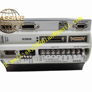
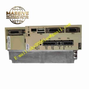
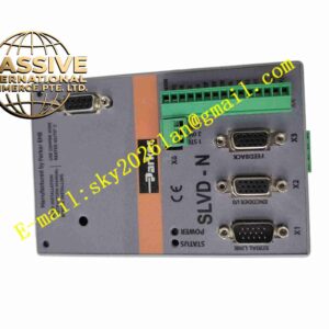
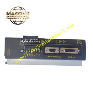
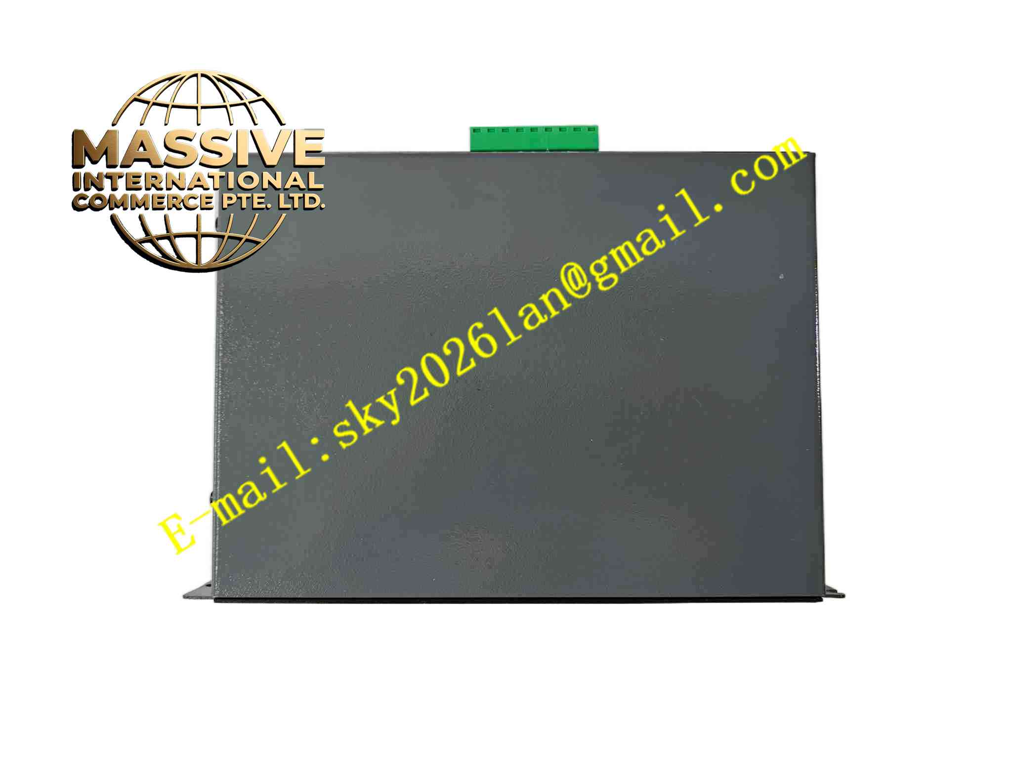
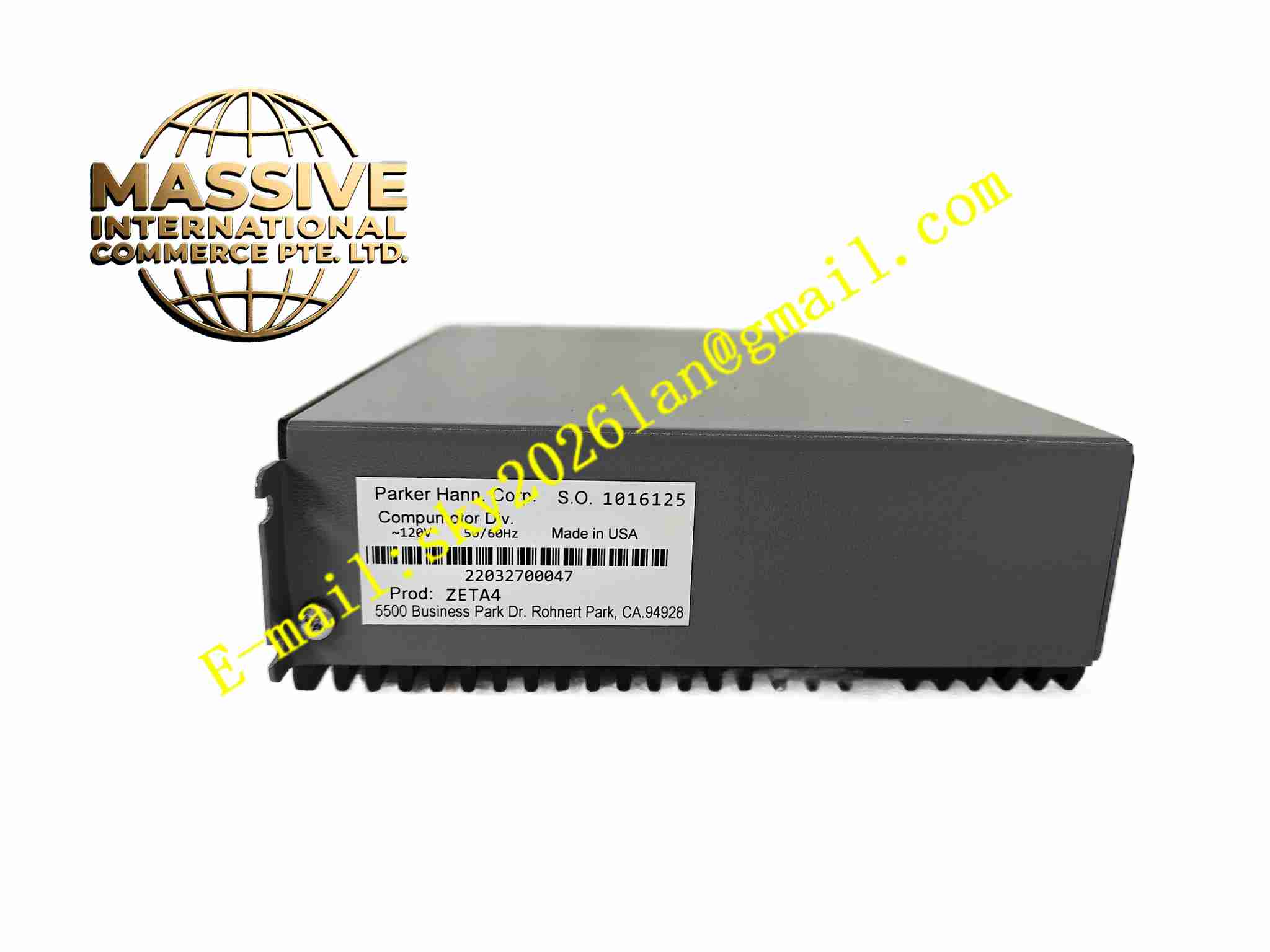
Parker ZETA4
Technical Specifications: Input voltage range: 115VAC / 230VAC single phase Continuous output current: 4A RMS Peak output current: 12A RMS Control loop update rate: 20kHz Feedback support: incremental encoder, Hall sensor Communication: RS232, analog command, pulse/direction input Digital I/O: 8 configurable digital inputs, 4 digital outputs Operating temperature range: 0℃ to 50℃ Storage temperature range: -20℃ to 85℃
Functional Features: Built-in auto-tuning function for quick adjustment of servo loop gains. Support position, velocity and torque three control modes. Integrated overcurrent, overvoltage, undervoltage, overtemperature, encoder fault protection. Parameter configuration and status monitoring via PC software. Electronic gearing function for multi-axis synchronization. Smooth velocity profile generation to reduce mechanical vibration.
Application Scenarios: Electronic assembly equipment, packaging machinery, semiconductor handling equipment, small CNC machine tools, laboratory automation platforms, textile machinery, precision conveyor systems.
Performance Parameters: Positioning accuracy up to encoder resolution limit. Bandwidth up to 1kHz. Full torque output at zero speed. Short circuit protection activates within 1 microsecond.
Material Composition: Aluminum alloy die-cast heat sink base. ABS plastic front housing. FR4 printed circuit board with industrial grade electronic components. Metal terminal blocks for power and signal wiring.
Structural Features: Compact vertical mounting structure. Integrated heat dissipation fins on the base plate. Separate terminal area for power wiring and signal wiring. LED indicator lights for power, fault and operation status. DIN rail mounting compatible.
Working Principle: The external motion command is received through analog signal or pulse input. The internal DSP processor calculates current, velocity and position closed-loop algorithm. PWM power module adjusts output voltage and current to drive servo motor. The feedback device sends real-time motor position and speed data back to the controller to continuously correct output, achieving closed-loop motion control.
Installation Requirements: Install on vertical DIN rail inside control cabinet. Maintain 25mm clearance above and below the unit for air circulation. Power cable and signal cable must run in separate cable ducts. Ground the housing to protective earth with 1.5mm² or thicker wire. Avoid installation near high-power contactors and transformers.
Usage Notes: Do not apply power before completing all wiring checks. Do not touch internal circuit board after power on. Match motor rated parameters with drive configuration before operation. Shut down power supply before replacing wiring or connectors. Keep the cabinet dust and moisture free.