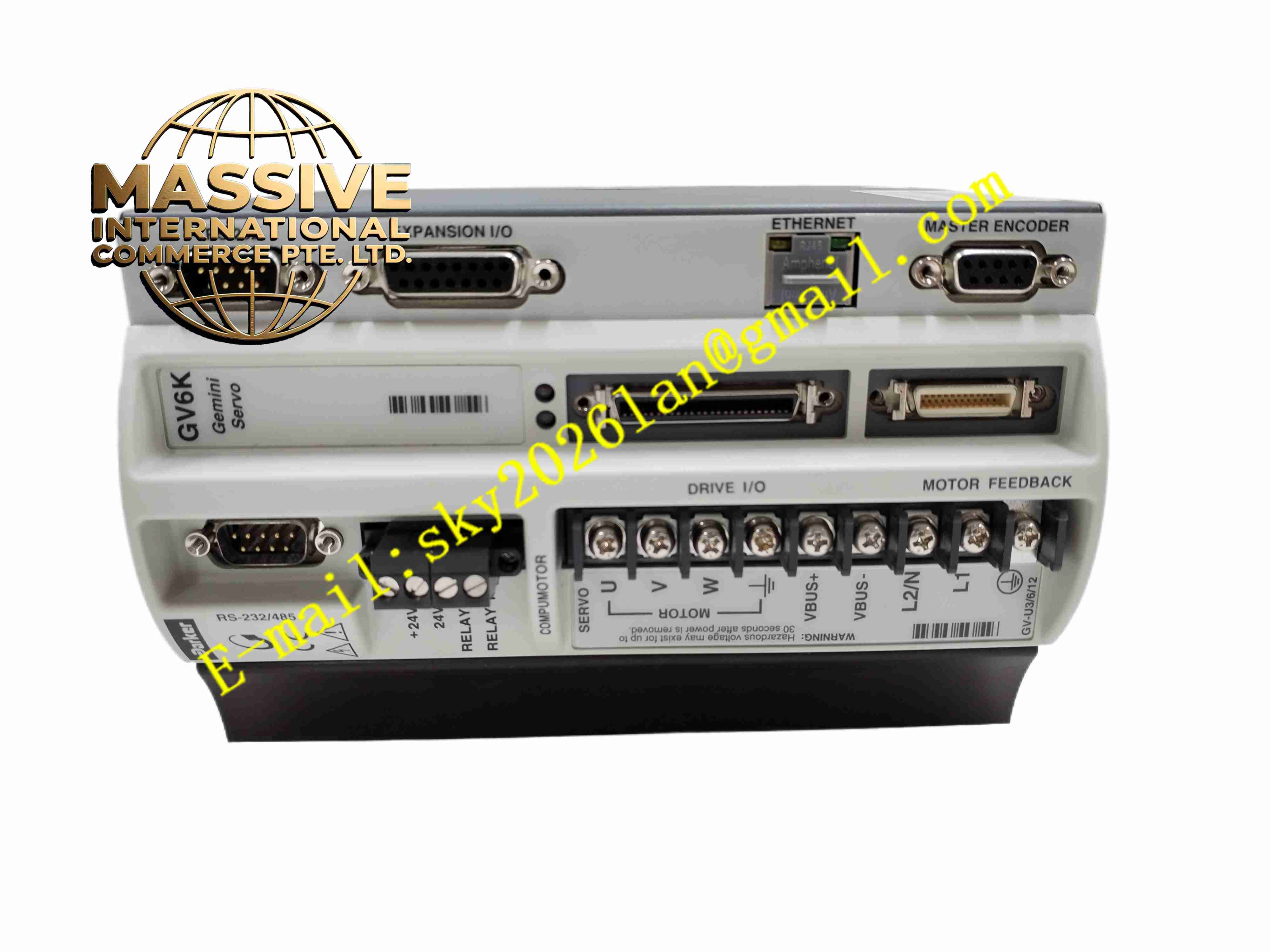
Description
Parker GV6K-U6E
Technical Specifications
- Product Type: Single axis digital servo drive
- Input Power: 110-240 V AC single phase
- Continuous Motor Output Power: 6 kW
- Control Signal Options: Step & direction, ±10 V velocity / torque command, RS232 / RS485 serial command
- Feedback Types: Incremental encoder, resolver
- Digital Inputs: 8 optically isolated discrete inputs
- Digital Outputs: 4 relay or open collector outputs
- Communication Interfaces: RS232, RS485
- Protection Functions: Overcurrent, overvoltage, undervoltage, overtemperature, encoder fault, motor overload
- Protection Rating: IP20
- Operating Temperature: 0 °C to +45 °C
- Mounting: Vertical panel mounting inside control cabinet
- Cooling: Forced air internal fan cooling
Functional Features
- Single axis closed-loop position, speed and torque control for brushed and brushless servo motors.
- Multiple command source selection supports pulse command, analog voltage and serial command.
- 8 optically isolated digital inputs accept home, limit, enable and machine interlock signals.
- 4 digital outputs provide fault, in-position and motion status signals to PLC.
- Built-in auto-tuning function optimises servo loop gain for different mechanical loads.
- Onboard motion profile generator executes point-to-point positioning without external pulse controller.
- Internal fault diagnostic function records fault code and waveform snapshot for troubleshooting.
- RS232 / RS485 serial port connects to PC configuration software or host PLC.
- Front panel LED indicators show power, run, fault and axis status.
- Overload and short circuit protection limits fault propagation to machine mechanics.
Application Scenarios
- CNC machine tool single axis servo positioning
- Automated cutting and laser processing equipment
- Material handling gantry axis motion control
- Printing and converting machinery servo drive
- Automated assembly station positioning axis
Material Composition
- Enclosure: Cold rolled steel metal casing with powder coating
- Main PCB: FR4 printed circuit board with conformal coating
- Power components: IGBT power switching modules
- Control processor: Industrial digital signal processor
- Terminal blocks: Tin-plated copper alloy screw terminals
- Communication connectors: D-Sub gold plated connectors for encoder and serial port
Structural Characteristics
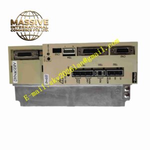
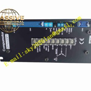
- Vertical rectangular metal cabinet structure for cabinet mounting.
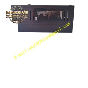
- Front panel with status LED indicators and ventilation grilles.
- Internal fan mounted at bottom for upward forced convection cooling.
- Rear terminal blocks for AC power, motor power, encoder and digital I/O wiring.
- Internal isolation barrier separates high voltage power circuit and low voltage signal circuit.
- Compact vertical form factor designed for installation in industrial control cabinet.
Working Principle Host controller sends motion command via pulse, analog voltage or serial communication to GV6K-U6E. Drive DSP compares command position and actual encoder feedback position, calculates control output through PID algorithm. IGBT power stage converts AC input power into variable frequency three-phase AC to drive servo motor. Encoder signal feeds back to drive continuously to close position loop. Digital I/O circuit reads machine limit and enable signals, and outputs motion status. When fault condition exceeds threshold, drive cuts motor power and latches fault alarm.
Installation Requirements
- Mount drive vertically inside control cabinet with specified clearance above and below for airflow.
- Use shielded twisted pair cable for motor power and encoder feedback wiring.
- Separate high power motor cable from low voltage signal cable in cable tray.
- Complete protective earth connection for drive metal housing.
- Execute motor setup and servo auto-tuning after wiring completion.
- Test limit switch, home switch and emergency stop interlock circuit.
- Verify encoder wiring polarity and count direction before full operation test.
Usage Notes
- Do not operate drive with cooling fan failure.
- Keep cabinet air inlet filter clean to prevent dust accumulation blocking airflow.
- Do not connect motor load exceeding rated power specification.
- Backup parameter settings before firmware upgrade or modification.
- Disconnect AC input power and discharge DC bus capacitor before wiring modification.
- Use anti-static wristband when handling encoder and control connectors.
- Replace drive immediately when permanent power stage or control hardware fault occurs.