Description
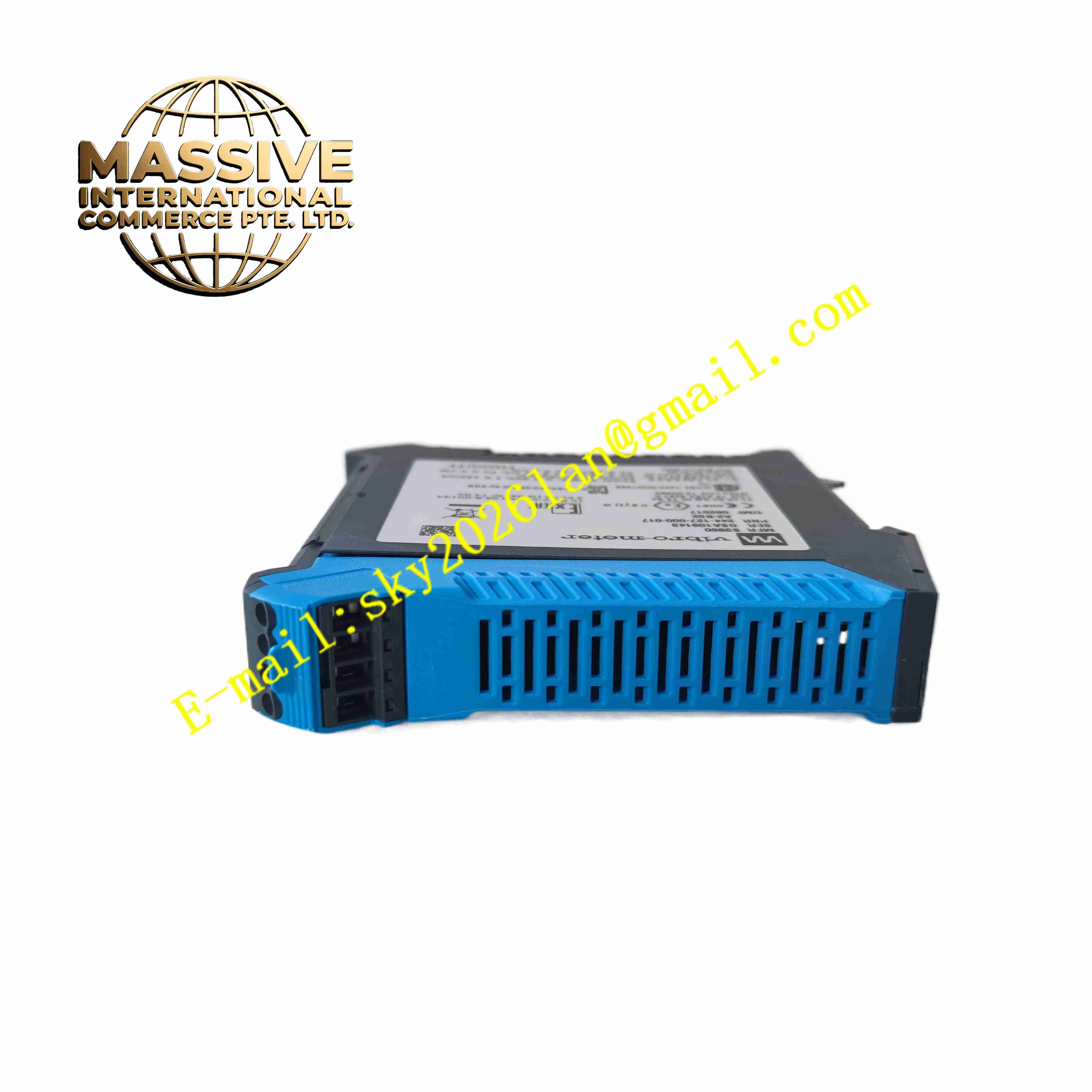
VIBRO-METER GSI127 244-127-000-017-A2-B02
Technical Specifications
- Product Type: Sensor power supply and galvanic isolation unit
- Power Input: 18 V DC to 30 V DC, max consumption 120 mA
- Galvanic Isolation: 4 kV RMS isolation between sensor side and monitor side; 50 V RMS isolation between power supply and signal output
- Transfer Function B02: 12 mA sensor input current converts linearly to 7 V DC output voltage
- Signal Compatibility: IEPE accelerometers, piezoelectric sensors, proximity probe signal conditioners
- Output Load Resistance: Maximum 10 kΩ, short circuit protected output circuit
- Protection Rating: IP20
- Operating Temperature: -40 °C to +85 °C
- Relative Humidity: 5 % to 95 %, non-condensing
- Mounting: Standard 35 mm DIN rail mounting
- Shock Resistance: 15 g peak half-sine shock, 11 ms duration
- Vibration Resistance: 5 g peak vibration 10 Hz to 500 Hz
Functional Features
- Regulated sensor power supply for IEPE accelerometers and Vibro-Meter signal conditioners.
- 4 kV RMS galvanic isolation breaks ground loops between field sensors and monitoring rack.
- Fixed linear current-to-voltage signal conversion for piezoelectric current output sensors.
- Built-in short circuit protection safeguards output circuit against field wiring faults.
- Continuous sensor loop diagnostic detects wire break and short circuit on sensor cable.
- Wide operating temperature range adapts to power plant and offshore cabinet environments.
- DIN rail compact form factor supports multiple units installed in same monitoring cabinet.
- High EMC immunity resists electrical noise from turbine, compressor and motor drives.
- SIL capable for safety-related machinery protection loops.
- Removable screw terminal blocks simplify field wiring and maintenance.
Application Scenarios
- Steam and gas turbine vibration monitoring signal isolation
- Centrifugal compressor condition monitoring measurement chain
- Power plant generator bearing vibration measurement
- Offshore platform rotating machinery protection system
- Petrochemical plant pump and fan vibration monitoring system
Material Composition
- Housing: Flame-retardant polycarbonate plastic enclosure
- Main PCB: FR4 printed circuit board with conformal coating
- Isolation components: High isolation transformers and optocoupler chips
- Power regulation components: Precision voltage regulator ICs
- Terminal blocks: Tin-plated copper alloy screw terminals
- Surge protection components: Transient suppression diodes
Structural Characteristics
- Slim single width DIN rail plastic housing.
- Front panel LED indicators for power and signal status.
- Rear removable screw terminal blocks for sensor wiring, power supply and signal output.
- Internal isolation barrier physically separates sensor side circuit and monitoring side circuit.
- Internal circuit layout minimizes cross-talk between low level vibration signals and power circuit.
- Passive convection cooling without fan components.
Working Principle 24 V DC auxiliary power feeds GSI127 internal power regulation circuit. The unit supplies constant excitation power to field piezoelectric or IEPE vibration sensors. Sensor outputs current signal proportional to vibration magnitude. Internal circuit converts sensor current signal to linear voltage output. High isolation barrier prevents ground potential difference between field machine and control cabinet from flowing through signal cable. Processed isolated voltage signal transmits to VM600 or other Vibro-Meter monitoring rack. Diagnostic circuit monitors sensor loop impedance continuously and reports wiring fault.
Installation Requirements
- Mount GSI127 on 35 mm DIN rail inside protected control cabinet.
- Use shielded twisted pair cable for sensor signal wiring.
- Separate sensor signal cables from high power motor and drive cables.
- Connect protective earth terminal to cabinet ground bar.
- Verify transfer function setting matches connected sensor type.
- Perform signal loop simulation test after wiring completion.
- Inspect shield termination to avoid multiple ground points for sensor cable.
Usage Notes
- Maintain single-point grounding rule for sensor cable shield.
- Do not apply voltage exceeding rated range to sensor input terminals.
- Keep cabinet dry and free of oil mist and corrosive vapor.
- Check terminal screw tightness periodically under high vibration environment.
- Disconnect power before modifying sensor wiring.
- Use anti-static wristband when handling the unit.
- Replace unit immediately when permanent isolation or signal conversion fault occurs.