Description
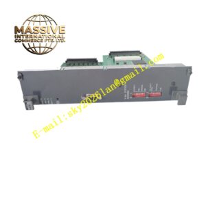
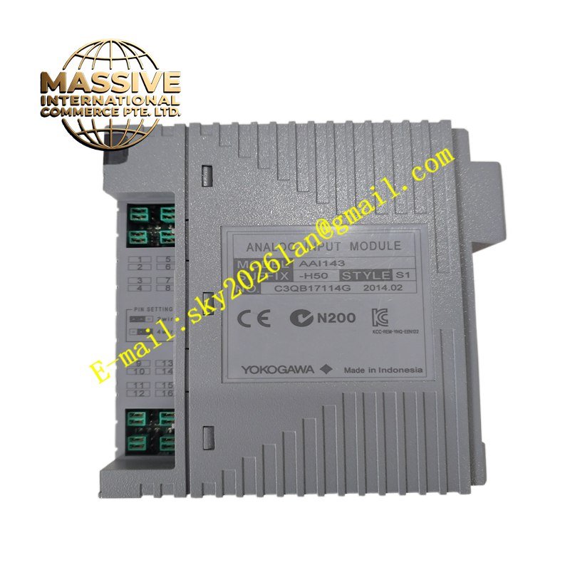
Yokogawa AAI143-H50K4A00
Technical Specifications 16 fully isolated input channels; input signal range 4 to 20mA; maximum allowable input current 24mA; isolation withstand voltage 1500V AC between field circuit and system backplane; input resistance 250Ω under powered state and above 500kΩ when power is off; basic measurement accuracy ±0.1% full scale; data update cycle 10ms; HART 5/6/7 protocol support; maximum power consumption 230mA under 5V DC internal supply and 540mA under 24V DC; operating temperature range -20°C to +70°C; protection class IP20; module weight approximately 0.3kg.
Functional Features Acquires continuous current signals from pressure, temperature, flow and level transmitters. Each channel implements independent electrical isolation to eliminate ground loop interference and crosstalk between measurement loops. Supports HART multiplexing to read secondary variables, device diagnostic status and perform remote parameter modification without on-site wiring adjustment. Detects open-loop and out-of-range signal faults and uploads alarm information to the DCS alarm manager. Supports wiring selection between pressure clamp terminals and MIL connector dedicated cables. Transmits digitized process measurement values to the field control node through the rack backplane bus.
Application Scenarios Petrochemical process monitoring, refining plant DCS cabinets, natural gas pipeline measurement loops, power plant auxiliary system analog signal acquisition, pulp and paper factory process parameter collection, pharmaceutical batch production control systems.
Performance Parameters Low temperature drift over full operating temperature band; stable measurement linearity across the entire 4-20mA span; fast response for closed-loop regulatory control; high electromagnetic compatibility for noisy industrial cabinet environments; consistent channel performance after long-term continuous operation.
Material Composition Main printed circuit board uses FR-4 flame-retardant multilayer substrate; analog front-end conversion chips are high-precision industrial semiconductors; isolation components adopt optocoupler isolation amplifiers; backplane gold finger connectors use gold-plated copper alloy contacts; outer housing is high rigidity flame-retardant thermoplastic resin; terminal contact pieces are nickel-plated copper alloy.
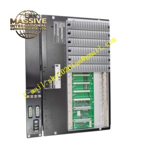
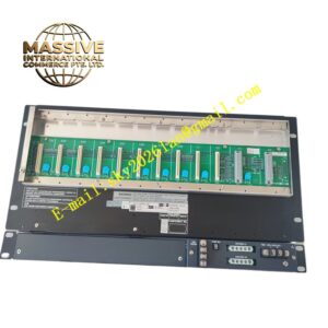
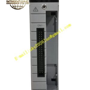
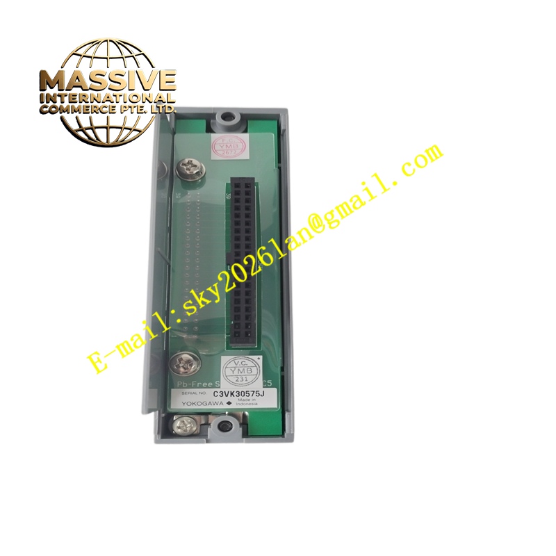
Structural Characteristics Compact vertical rack plug-in form factor matching Yokogawa ANB10, ANB11, ANT10 and AFV30/40 base units. Front panel carries channel status LEDs, power indicator and fault indicator. Rear gold finger connector mates with the control rack backplane for power and bus communication. Side mechanical latch locks the module firmly in the slot. External wiring connects through dedicated KS cable and MIL connector adapter defined by the K4A00 option code.
Working Principle Analog 4-20mA current signals from field transmitters flow into the module’s signal conditioning circuit. The circuit implements current limiting, filtering and isolation processing. High-resolution analog-to-digital converters convert analog current values into digital measurement data. The onboard microcontroller packages measurement data and HART digital data, then transmits data frames to the FCN controller through the backplane bus. Built-in monitoring circuits continuously judge signal amplitude and identify wire break or short-circuit faults on each channel.
Installation Requirements Cut off rack power before inserting or removing the module. Align the module with the rack slot guide rails and push fully until the latch clicks into place. Match the ATK4A-00 adapter and KS MIL connector cable according to the K4A00 wiring scheme. Use twisted shielded instrument cables for field transmitter wiring and complete single-point shielding grounding. Configure signal range and alarm thresholds in Yokogawa engineering software and perform loop calibration before commissioning.
Precautions for Use Do not feed AC high voltage directly into the 4-20mA input terminals. Keep the module ventilation gaps free of dust and conductive debris. Route analog signal cables separately from high-power inverter and motor cables. Confirm HART protocol compatibility when connecting multi-drop smart transmitters. Implement anti-static protection when handling the module out of the rack.