Description
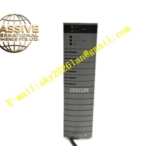
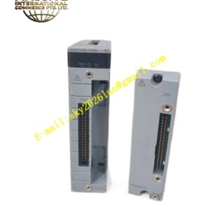
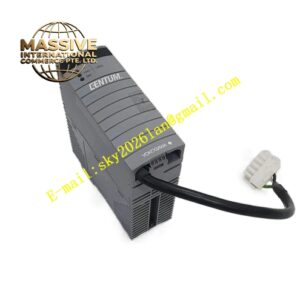
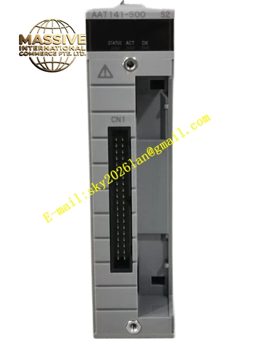
YOKOGAWA AAT141‑S00
Technical Specifications: Supported input‑signal types: Pt100, Pt50 RTD sensors; K, J, T, E type thermocouples; total channel quantity: 16 channels; channel‑to‑channel galvanic isolation; analog‑to‑digital conversion resolution: 16‑bit; supports open‑wire detection for sensor circuits; cold‑junction compensation function for thermocouple inputs; operating power draws from CENTUM‑VP rack backplane bus; operating temperature: 0 °C‑60 °C; storage temperature:‑20 °C‑70 °C; relative humidity: 10‑90 %RH non‑condensing; FIO rack‑slot mounting; front‑panel LED indicators for RUN status, module fault and channel diagnostic alarms; weight: 0.81 kg.
Functional Features: Sixteen‑channel isolated temperature signal acquisition for RTD and thermocouple sensors; built‑in cold‑junction compensation circuit ensures thermocouple measurement accuracy; per‑channel open‑wire detection identifies broken field‑sensor wiring; channel‑wise galvanic isolation eliminates ground‑loop interference coming from distributed field‑sensor loops; hardware self‑diagnosis detects module internal hardware defects and backplane‑bus communication abnormalities; front‑panel LED status group provides visual RUN and fault indication; transmits converted digital temperature measurement data to CENTUM‑VP CPU via rack backplane bus.
Application Scenarios: Chemical‑plant reactor and furnace temperature‑monitoring loops; petrochemical refinery process‑pipe temperature measurement; power‑plant boiler‑system temperature‑point acquisition; oil‑gas processing plant process‑temperature monitoring; CENTUM‑VP DCS system spare‑part replacement and maintenance projects.
Performance Parameters: Temperature‑measurement accuracy satisfies CENTUM‑VP DCS process‑control requirements; channel‑to‑channel isolation dielectric strength conforms to process‑instrument industrial standards; vibration and shock resistance meets cabinet‑mount control‑hardware criteria; supports continuous 24‑7 operation inside non‑condensing industrial control cabinets.
Material Composition: Orange V0 flame‑retardant engineering‑plastic rack‑module housing; FR‑4 multi‑layer glass‑fiber printed circuit board; high‑precision analog‑to‑digital conversion chips; per‑channel galvanic isolation components; cold‑junction‑compensation temperature‑sensing elements; gold‑plated backplane edge‑connector contacts; multi‑color SMD LED status indicators; metal mechanical locking latches.
Structural Features: Standard CENTUM‑VP FIO rack‑slot physical dimension; rear‑side gold‑plated edge‑connector interfaces with rack backplane bus; front‑panel mounts RUN and fault‑status LED indicators; side metal latches lock module securely into FIO rack I/O slot; field‑sensor wiring completes externally through compatible FIO terminal‑block assembly.
Working Principle: Field RTD or thermocouple sensor signals pass through matched terminal‑block assembly and feed into AAT141‑S00 input channels. For RTD input channels, analog front‑end applies constant excitation current and measures voltage drop proportional to sensor resistance value. For thermocouple channels, circuit captures thermoelectric voltage value, and cold‑junction‑compensation circuit compensates terminal‑block ambient‑temperature offset. Galvanic isolation circuits separate field‑side analog signal domain from module internal digital‑logic domain. Analog‑to‑digital converter transforms analog measurement values to 16‑bit digital data. Digital measurement data transmits to CENTUM‑VP CPU through rack backplane bus. Onboard diagnostic logic detects open‑wire sensor faults and internal‑module hardware failures, and drives front‑panel LED indicators accordingly.
Installation Requirements: Insert AAT141‑S00 into valid I/O slot of CENTUM‑VP FIO main rack or expansion rack; engage side mechanical latches for reliable mechanical fixation; use matched terminal‑block assemblies for all field‑sensor wiring; deploy shielded twisted‑pair cables for temperature‑sensor signal transmission; separate analog‑sensor cables from high‑power motor and inverter power cables; implement reliable protective grounding for control cabinet and rack assembly.
Usage Notes: Follow official hot‑swap operation procedures for module replacement on powered‑on rack; configure sensor‑type and measurement parameters inside CENTUM‑VP engineering software during commissioning; verify RTD wiring or thermocouple polarity correctness to avoid measurement deviation; avoid deployment in environments with corrosive gas, liquid splash or condensation; inspect terminal‑block screw tightening torque during periodic system‑maintenance cycles.