Description
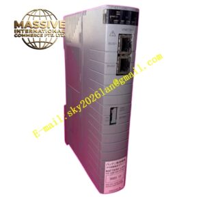
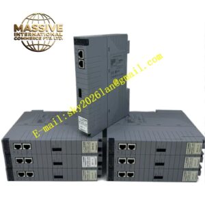
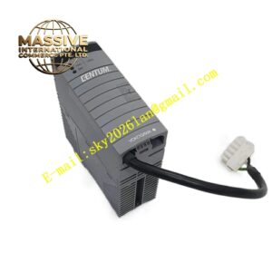
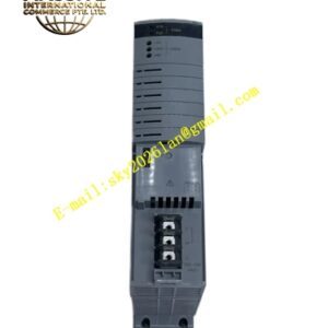
YOKOGAWA EC401‑10
Technical Specifications: Communication function: CENTUM‑VP expansion‑rack interconnection bus; dual‑port redundant communication interface; real‑time bidirectional data transmission between main rack and expansion racks; communication physical layer uses differential signal transmission; operating power draws from rack backplane bus; operating temperature: 0 °C‑60 °C; storage temperature:‑20 °C‑70 °C; relative humidity: 10‑90 %RH non‑condensing; CENTUM‑VP rack‑slot mounting; front‑panel LED indicators for link active status, communication run status and fault alarm; weight: 0.76 kg; supports automatic redundant‑channel switch‑over.
Functional Features: Dual‑channel redundant bus communication connects main control rack with multiple expansion I/O racks; bidirectional real‑time transmission of process I/O data, module diagnostic information and system operating status; automatic switch‑over to backup communication channel upon primary link fault without interrupting system operation; continuous hardware self‑diagnosis detects internal module defects and inter‑rack bus communication abnormalities; front‑panel LED group delivers direct visual indication for link activity and fault events; maintains full compatibility with all CENTUM‑VP series I/O modules inside expansion racks.
Application Scenarios: Large‑scale CENTUM‑VP DCS projects requiring multi‑rack distributed I/O deployment; petrochemical plant control cabinets with large quantity of field instrument points; chemical‑industry process control systems needing expansion‑rack I/O extension; power‑plant auxiliary‑control distributed I/O cabinets; CENTUM‑VP system hardware upgrade and spare‑part replacement projects.
Performance Parameters: Redundant‑bus switch‑over finishes without real‑time data loss; communication signal maintains stable performance under industrial‑field electromagnetic interference environment; vibration and shock resistance conforms to process‑control cabinet‑mount hardware standards; supports 24‑7 continuous long‑term operation under non‑condensing indoor cabinet conditions.
Material Composition: Orange V0 flame‑retardant engineering‑plastic rack‑module housing; FR‑4 multi‑layer glass‑fiber printed circuit board; industrial‑grade differential signal transceiver chips; communication processing integrated circuits; gold‑plated backplane edge‑connector contacts; multi‑color SMD LED status indicators; metal mechanical locking latches.
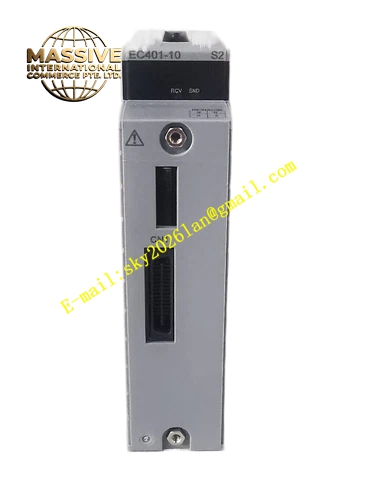
Structural Features: Standard CENTUM‑VP rack‑slot form factor; rear‑side gold‑plated edge‑connector interfaces with main‑rack backplane bus; front‑panel mounts dual redundant bus signal connectors and status‑LED indicator bank; side metal latches lock module firmly into communication slot position of control rack; housing ventilation slots implement passive convection cooling design.
Working Principle: EC401‑10 receives control‑station CPU data and I/O read‑write commands via rack backplane bus. Internal communication processor packages data frames and transmits information through dual differential bus ports to corresponding EC401‑10 modules installed inside expansion racks. Incoming data frames coming from expansion racks receive signal validation and error check before forwarding to main‑rack CPU through backplane bus. When primary communication channel suffers signal attenuation or cable damage, hardware logic switches all data traffic to secondary redundant channel automatically. Onboard diagnostic circuits monitor signal integrity and module hardware state continuously, trigger corresponding fault‑status LED when abnormality gets detected.
Installation Requirements: Insert EC401‑10 into designated communication slot of CENTUM‑VP main control rack; lock side mechanical latches to complete firm mechanical fixation; deploy Yokogawa‑approved shielded inter‑rack communication cables for redundant‑bus wiring; separate inter‑rack communication cables from high‑power motor and inverter power cables; ensure control cabinet and rack obtain reliable protective grounding.
Usage Notes: Execute official hot‑swap operation procedures for module replacement on powered‑on rack; strictly use manufacturer‑recommended communication cables for inter‑rack bus connection; verify redundant‑channel switch‑over performance during system commissioning phase; avoid deployment in environments with corrosive gas, liquid splash or condensation; check communication‑connector locking condition during regular maintenance cycles.