Description
ABB REF541
Technical Specifications
| Parameter | Value / Description |
|---|---|
| Current Inputs | 3 × phase CT (1 A / 5 A selectable), 1 × neutral CT (I0); burden ≤0.1 VA @ 1 A / ≤0.2 VA @ 5 A |
| Voltage Inputs | 3 × phase VT (100 V / 110 V / 120 V L-L), 1 × Vn (optional 4-wire V0); burden ≤0.2 VA |
| Protection Functions (typical set) | 51 / 67 (phase OC, dir opt), 51N / 67N (EF, dir opt), 46 (neg seq unbalance), 49 (thermal image), 21 (undervoltage dir opt), 59 (overvoltage), 81O/U (freq), 79 (auto-reclose), 50BF (breaker fail), 25 (synchro-check – opt), VTFF (VT fuse fail) |
| Binary Inputs (BI) | 8–14 (model dep.) — wet (110/220 V DC) or dry (24 V DC) contact; typical assignments: 52a/b (breaker pos), ext trip/block, test/disable, close perm, local/remote sel |
| Binary Outputs (BO) | 8–14 — SPDT/SPST relay contacts; typical: Trip (2x redundant), Close, Alarm, Healthy, Opr Counter, Test |
| Trip Contact Rating | 5 A @ 250 V AC / 30 V DC (make & break — verify per model label) |
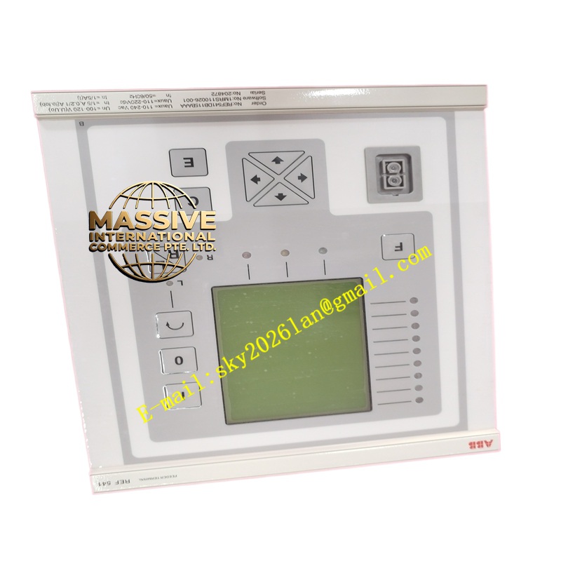
| Display | Graphical LCD (320×240 or 640×480) + keypad — local setting, event/fault review, analog measurements |
| Time Synchronization | IRIG-B, SNTP, PTP (IEEE 1588 v2 – opt) |
| Disturbance Recorder | ≥50 COMTRADE files; pre-fault ½ cycle + post-fault up to several cycles; sampling up to 4 kHz |
| Power Supply | 110/220 V DC ±20 % or 230 V AC ±15 % (dual redundant PSU option) |
| Operating Temperature | –20 °C to +55 °C (storage –40 °C to +70 °C) |
| Ingress Protection | Front IP54 (with gasket), rear IP20 |
| Case / Mounting | 4U half-rack 19″ panel-mount OR DIN-rail compact (REF541C compact version); weight ≈4–6 kg |
| Certifications | IEC 60255, IEC 61850-3/5-7, IEEE C37.90, KEMA type-tested, CE, UL, cUL |
| Engineering Tool | ABB PCM600 (Protection & Control Configuration Tool) — SCL (SCD/CID) import/export for IEC 61850 |
Functional Features
- Integrated Bay Control: Start/Stop (Close/Open) pushbuttons on front or via binary inputs; local/remote selector; 2-wire (maintained) or 3-wire (momentary) control; anti-pumping logic built-in.
- Dual Setting Groups: Easily switch between seasonal / alternate network configurations (e.g., radial vs. looped).
- Disturbance Analysis: On fault trip, REF541 auto-records current/voltage waveforms → download via PCM600 or via station bus for fault type & location analysis.
- IEC 61850Native: Acts as an IED in a process/station bus architecture — publishes measured values (MV), status (GOOSE), receives intertripping GOOSE from bus differential (e.g., RET670/REF615).
- Self-Monitoring: Continuous self-check; watchdog; loss of CT/VT signals flagged; PSU fail contact.
- Thermal Image (49): Simulates motor/heater thermal accumulation — accounts for start-up heating & cooling tail — trips on over-temperature.
- Password / Role-Based Access: Prevent unauthorized setting changes; audit trail of who changed what.
Application Scenarios
- 11 kV / 22 kV / 33 kV / 66 kV Radial or Ring-Main Feeder Protection — OC + EF + Auto-Reclose
- Transformer LV (Secondary) Side Protection — OC + EF + thermal + inrush restraint (2nd harmonic restraint available on some RET54x — REF541 typically gets inrush block signal from HV side differential)
- Reactor / Capacitor Bank Feeder Protection — OC + unbalance (via V or I inputs)
- Industrial Substation Bay Unit — integrates protection + control + metering in one device; reports to SCADA/DCS via IEC 61850 or Modbus/DNP3
- Retrofit of Legacy Electromechanical / Static OC-GEF Relays — single device replaces multiple panels; adds disturbance recording & communications
Material Composition & Structural Characteristics
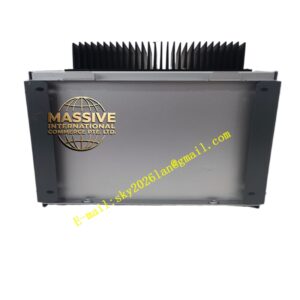
- Housing: Sheet steel / aluminum alloy case (panel-mount) or flame-retardant polycarbonate (compact DIN version); front bezel gray (RAL 7035) with transparent Lexan window.
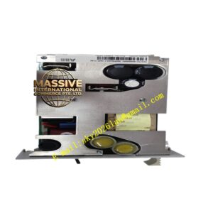
- Terminals: Rear plug-in screw / spring-cage terminals for CT, VT, DC supply, BI/BO — keyed to prevent mismating; option for plug-in terminal blocks (easier replacement).
- Display: Backlit monochrome or color LCD (model dependent); tactile keypad with soft-keys + navigation arrows + numeric entry.
- Internal: Multilayer PCB with 16/32-bit processor, A/D front-end with anti-alias filter, RTC with supercap backup (≥10 yr typical), galvanically isolated CT/VT inputs (≥2 kV impulse).
- Cooling: Passive convection (no fan in standard REF541).
Working Principle
- Sampling: CT secondaries (Ia,Ib,Ic,In) and VT secondaries (Vab,Vbc,Vca,Vn) are continuously sampled via precision A/D converters (typically 24 samples/cycle → 1.2 kHz for 50 Hz systems).
- Protection Algorithms:
- Overcurrent (51/67): RMS of phase currents computed via DFT; compared to pick-up × time dial curve (IEC / IEEE standard inverse, very inverse, extremely inverse, definite time). If directional element enabled → compare phase angle of I with polarized V (or residual I0/E0) → only trip if fault in forward direction.
- Earth Fault (51N/67N): Residual I0 (3I0 = Ia+Ib+Ic) or core-balance CT (CbCt) → RMS compared to pick-up; directional EF uses V0 polarization.
- Thermal Image (49): Integrates I²×R heating; cools per exponential decay (τ = thermal time constant); trips if θ ≥ alarm / trip threshold.
- Auto-Reclose (79): On trip → start reclose timer (dead time) → issue Close cmd → if persistent fault → lockout (after N shots); if successful → reset.
- Trip Decision: If any enabled protection element asserts → Trip relay picks up → closes NO contact in breaker trip circuit (typically via auxiliary tripping relay or direct if contact rating sufficient & scheme allows).
- Recording: Pre-fault + fault + post-fault samples stored as COMTRADE; SOE time-stamped to RTC (IRIG-B/NTP synced).
- Communication: Periodic MMS reports (measured values, quality, health) + GOOSE publish/subscribe for inter-IED signaling (e.g., bus differential blocking OC during close-in fault).