



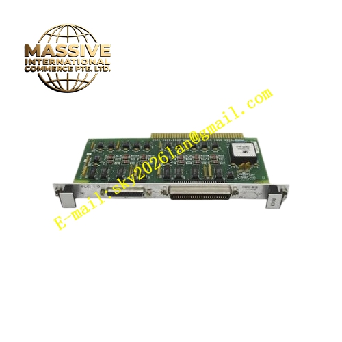
Description
Honeywell 51196714-100
Technical Specifications
- Redundancy Link Speed: 10Mbps dedicated differential link
- Link Medium: Shielded twisted pair cable
- Power Supply: 5VDC and 12VDC from rack backplane
- Operating Ambient Temperature: 0°C to +60°C
- Storage Temperature: -40°C to +85°C
- Relative Humidity: 5% to 90% RH non-condensing
- Mounting Type: Plug-in slot installation on TDC3000 processor rack
- Certification: UL, CE, RoHS
- Link Channel Quantity: Dual redundancy link support
Functional Features It transmits real-time database synchronization data between primary and standby processor. It exchanges heartbeat packet at fixed interval to judge peer processor health status. It synchronizes PID output, sequence step status and alarm latch state continuously. It triggers bumpless redundant switchover within preset time when primary heartbeat is lost. It carries dual link path to avoid single link failure. It reports link disconnection, synchronization timeout and heartbeat loss fault to TDC3000 operator station. It carries front panel LED indicators for power, primary active, standby active and link fault. It supports hot swap replacement in redundant processor rack. It records switchover event log and fault timestamp in non-volatile memory.
Application Scenarios TDC3000 redundant control processor synchronization link Petrochemical plant reactor high-availability control node Refinery furnace safety interlock redundant processor rack Power plant boiler combustion control redundant node Chemical plant batch process uninterrupted control cabinet
Performance Parameters
- Redundancy Switchover Time: Less than 40ms
- Mean Time Between Failures: 870000 hours
- ESD Immunity: 8kV contact discharge
- Maximum Supported Cable Length Between Two Processors: 100 meters
- Synchronization Data Refresh Cycle: 10ms
Material Composition FR4 flame retardant conformal coated multilayer PCB High-speed differential communication transceiver chip Heartbeat monitoring logic FPGA chip Dual channel isolation transformer network TVS surge suppression diodes Backplane bus interface chip Gold plated edge connector for TDC3000 processor backplane Metal front panel with extraction handle, terminal block and LED indicators
Structural Features Standard TDC3000 paddle card form factor. Front panel integrates removable shielded twisted pair terminal block, grouped LED indicators and extraction handle. Rear gold plated edge connector mates with processor backplane power and logic bus. Dual redundancy link circuits adopt independent isolation and shielding layout to avoid mutual interference. Anti-key notch prevents reverse insertion into rack slot. Locking clip secures module firmly after installation. Conformal coating fully covers PCB surface to resist dust and moisture in industrial cabinet. Differential signal traces adopt controlled impedance design.
Working Principle After receiving power supply from backplane, the module completes self-test and link initialization. Primary processor sends database snapshot, loop state and heartbeat packet through redundancy link. Standby processor receives synchronization data and keeps its internal database consistent with primary processor. Logic chip monitors heartbeat packet arrival interval continuously. If heartbeat packet is not received within timeout window, the module sends failure signal to trigger standby processor to take over control. Switchover event and fault information are uploaded to TDC3000 operator station.
Installation Requirements Wear anti-static wrist strap before inserting module into dedicated redundancy slot of each processor in redundant pair. Lock extraction handle after full seating. Connect shielded twisted pair cable between the two redundancy link boards. Configure redundant node identification and switchover parameters in engineering workstation. Power on rack and verify one processor active LED steady on. Test bumpless switchover by powering off primary processor. Confirm control loop output keeps stable without bump.
Usage Notes Use shielded twisted pair cable for redundancy link wiring and single point shield grounding. Do not route redundancy cable together with high voltage power cable. Check link terminal screw tightness periodically under vibration environment. Replace module when continuous synchronization timeout alarm occurs and cable is intact. Do not remove one redundancy link board while the redundant node is running.







