



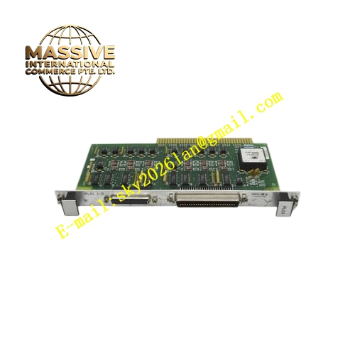
Description
Honeywell 51197020-100
Technical Specifications
- Bus Standard: Honeywell UCN bus, 5Mbps
- Optical Interface: Multimode fiber, ST connector
- Wavelength: 850nm
- Maximum Fiber Transmission Distance: 2000 meters
- Power Supply: 24VDC from rack backplane
- Operating Ambient Temperature: 0°C to +60°C
- Storage Temperature: -40°C to +85°C
- Relative Humidity: 5% to 90% RH non-condensing
- Mounting Type: Plug-in slot installation on TDC3000 rack
- Certification: UL, CE, RoHS
- Electrical Side Interface: UCN shielded twisted pair terminal block
Functional Features It converts electrical differential UCN signal into modulated optical signal for fiber transmission. It converts received optical signal back to standard UCN electrical differential signal at remote end. It supports redundant UCN A and UCN B dual fiber channel. It monitors optical power loss, fiber breakage and transceiver fault. It carries front panel LED indicators for power, optical link active and fiber fault. It supports hot swap replacement in non-critical rack configuration. It uploads optical power value and fiber break alarm to TDC3000 operator station. It isolates ground potential difference between different plant marshalling cabinets. It eliminates electromagnetic induction interference from high voltage power lines crossing the route.
Application Scenarios Cross-area remote UCN bus extension for TDC3000 system Petrochemical plant UCN network across furnace and tank farm area Refinery remote UCN I/O cabinet fiber connection Power plant boiler island and auxiliary building UCN fiber link Chemical plant remote reactor UCN controller fiber communication
Performance Parameters
- Mean Time Between Failures: 770000 hours
- ESD Immunity: 8kV contact discharge
- Optical Receiver Sensitivity: -31dBm
- Optical Transmit Power: -12dBm nominal
- Bit Error Rate: Less than 10⁻¹²
Material Composition FR4 flame retardant conformal coated multilayer PCB Multimode optical transmit and receive transceiver pair UCN differential signal amplifier and shaping circuit Optical power monitoring detection circuit TVS surge protection components for electrical UCN side Gold plated edge connector for TDC3000 rack backplane Metal front panel with extraction handle, ST fiber ports, UCN terminal block and LED indicators
Structural Features Standard TDC3000 paddle card form factor. Front panel integrates dual ST fiber connectors, UCN twisted pair terminal block, grouped LED indicators and extraction handle. Rear gold plated edge connector mates with rack backplane 24VDC power and monitoring signal pins. Optical transceiver circuit and electrical UCN circuit are fully isolated to eliminate ground loop current. Anti-key notch prevents reverse insertion into rack slot. Locking clip secures module firmly after installation. Conformal coating fully covers PCB surface to resist dust and moisture in industrial cabinet environment.
Working Principle After receiving 24VDC power supply from rack backplane, the module completes power-on self-test of optical transceiver. Electrical UCN differential signal enters shaping amplifier circuit and drives optical transmitter to modulate 850nm optical signal. Optical signal transmits through multimode fiber cable to remote extender module. Remote optical receiver converts optical signal back to differential electrical UCN signal and sends to remote UCN bus. Optical power detection circuit continuously monitors received optical power. If optical power drops below threshold, fiber break fault flag generates and alarm uploads to TDC3000 operator station.
Installation Requirements Wear anti-static wrist strap before inserting module into dedicated UCN extender slot of rack. Lock extraction handle after full seating. Connect UCN twisted pair cable to electrical side terminal block. Clean ST fiber connector end face before plugging into fiber port. Configure optical link alarm threshold in engineering workstation. Power on rack and verify optical link active LED steady on. Test fiber break alarm by disconnecting fiber connector temporarily. Verify UCN device communication keeps stable through fiber link.
Usage Notes Do not look directly at optical transmitter port to avoid eye injury. Keep ST fiber connector end face clean and protected by dust cap when not connected. Avoid sharp bending of fiber optic cable, minimum bend radius must comply with fiber specification. Do not route fiber cable together with high voltage power cable. Replace module when optical link alarm persists and fiber cable is intact.







