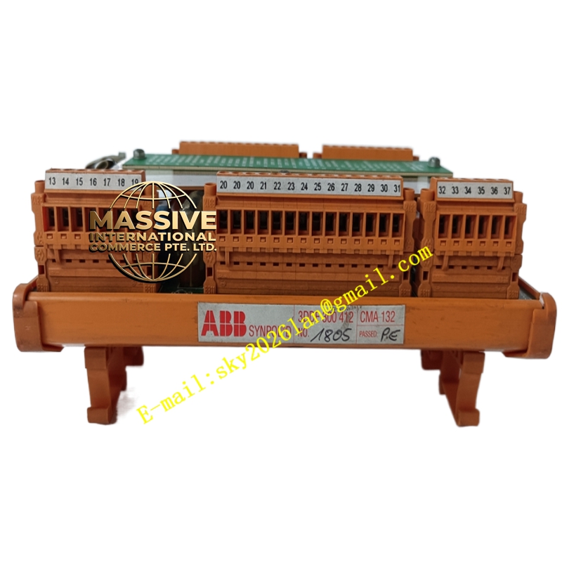
Description
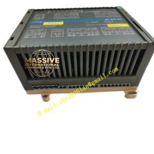
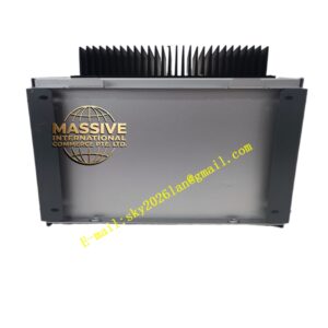
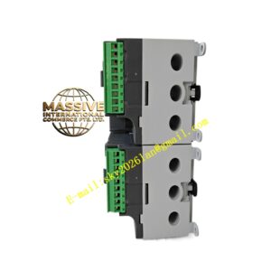
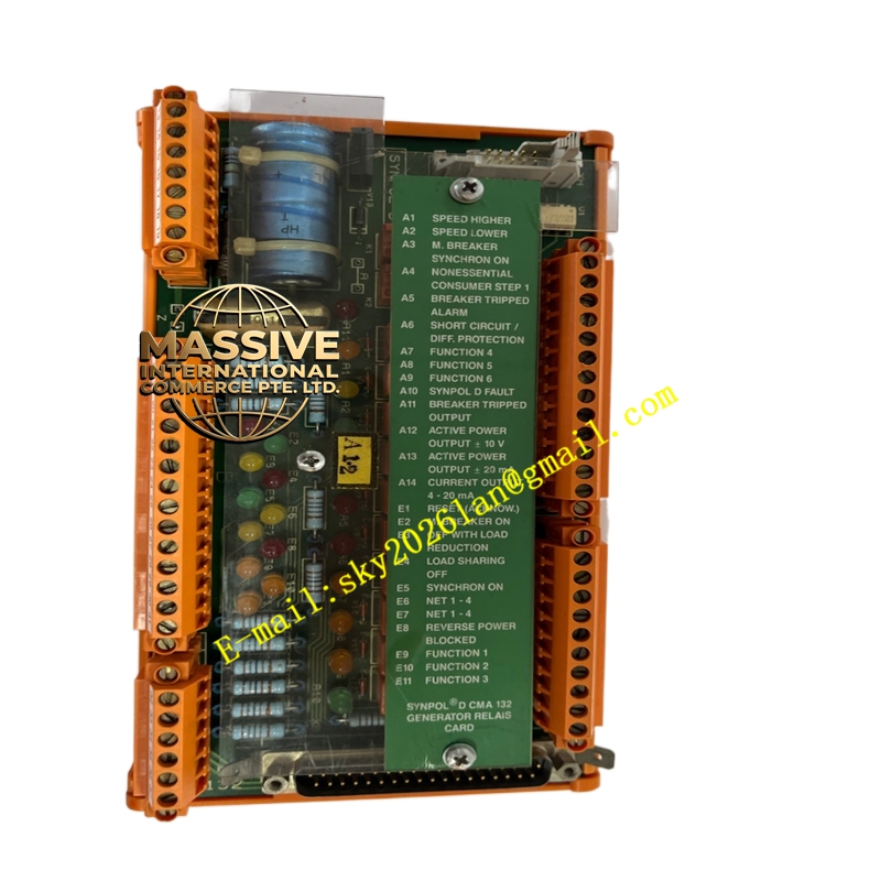
ABB CMA132 3DDE300412
Technical Specifications & Performance Parameters
- Channel Configuration: 16-channel multi-function signal input channels, support thermocouple, RTD, mV, mA, voltage, resistance potentiometer signal access
- Signal Conversion Parameters:
- Input power supply: 24VDC ±20% auxiliary power
- Input loop maximum current: 5mA per channel
- Analog output signal standard: 0–10VDC voltage signal, 4–20mA DC current signal
- Isolation Index: 1500VAC isolation voltage between each signal channel and internal power circuit, channel-to-channel independent isolation
- Resolution Performance: 16-bit AD/DA digital conversion precision
- Display Function: 4-digit front panel LED digital tube display real-time channel measured value
- Communication Interface: Onboard Modbus RTU RS485 communication bus interface
- Environmental Parameters:
- Operating temperature: -40°C ~ +85°C
- Storage temperature: -40°C ~ +85°C
- Humidity range: 5%–95% non-condensing
- Protection Grade: Front panel IP65, circuit board inner layer IP20
- Mounting Mode: Cabinet panel fixed mounting or DCS rack plug-in optional
Function Characteristics
- Multi-type universal signal input channel, compatible with all standard generator measurement sensor signals without external signal converters
- Independent electrical isolation between each channel, eliminate cross-channel signal interference caused by power station ground potential difference
- Analog signal two-way conversion: convert field weak sensor signals into standard 4–20mA/0–10V signals transmitted to DCS main control module
- Built-in signal overvoltage and overcurrent protection circuit, automatically block abnormal signal input to protect rear-end CMA126 main control module
- Modbus RTU communication function, upload each channel real-time measurement data to upper monitoring equipment independently
- Adjustable signal filtering parameters, filter power frequency interference noise of power station strong electromagnetic environment
- Front panel digital display, on-site staff can directly read measurement values without upper computer operation
- Channel fault self-diagnosis, detect sensor open circuit, short circuit and output fault code on digital tube
Material Composition
- Front panel: Flame-retardant PC plastic with waterproof and dustproof sealing rubber ring
- Circuit substrate: Multi-layer isolation FR4 PCB, independent isolation optocoupler components for each channel
- Wiring terminal: Copper alloy nickel-plated spring clamp terminals, anti-loose vibration resistant
- Digital display unit: High-brightness anti-interference LED digital tube, anti-glare surface coating
Structural Features
- Standard 48mm × 96mm panel size, compatible with general DCS cabinet panel mounting hole size
- Split front display panel and rear wiring terminal area, convenient for wiring without shielding digital display
- Independent isolation cavity for each signal channel on internal circuit board to reduce signal crosstalk
- Built-in heat dissipation micro-slots on the shell, adapt to wide temperature range operation without cooling fan
- Anti-vibration fixed buckle structure, suitable for long-term vibration environment of generator room
Working Principle
- Field generator sensor signals access each independent isolation channel of the terminal board through wiring terminals
- Weak analog signals pass through isolation optocoupler and signal conditioning circuit, convert into standard industrial 4–20mA/0–10V analog signals
- Onboard 16-bit AD chip converts analog signals into digital quantity, transmit to CMA126 main control module through DCS backplane bus
- Real-time measured value displayed on front panel LED digital tube, and data uploaded to upper monitoring system via Modbus RS485 bus
- When channel signal is abnormal (open circuit, short circuit), internal fault detection circuit triggers digital tube fault code display and upload fault signal to DCS system
Installation Requirements
- Two installation modes: Cabinet embedded panel mounting or DCS standard rack plug-in installation
- Signal wiring must use shielded twisted pair, each channel wire independently routed to avoid parallel high-power cable
- 24VDC auxiliary power supply matched with independent fuse, rated fuse current 0.25A
- Installed position away from generator high-voltage cabinet, maintain more than 1.5m distance to reduce electromagnetic interference
- Cabinet ground bar connected to terminal board grounding terminal with 1.5mm² copper wire
Application Scenarios
- Thermal power generator temperature, vibration, pressure sensor signal collection
- Hydraulic turbine generator bearing temperature monitoring signal conversion
- Generator excitation cabinet protection relay signal isolation transmission
- Power plant boiler auxiliary equipment analog signal terminal distribution
- Substation auxiliary power system multi-channel signal centralized acquisition
Usage Precautions
- Do not mix AC high voltage signal and low voltage sensor signal into the same channel terminal
- When modifying channel signal type parameters, cut off auxiliary power supply first to avoid AD chip damage
- Regularly check wiring terminal spring clamp tightness to prevent loose contact caused by unit vibration
- Avoid long-term exposure to oil mist and corrosive gas environment, regularly wipe front panel dust with dry cloth
- When Modbus communication data loss occurs, check bus shielding grounding and terminal matching resistance