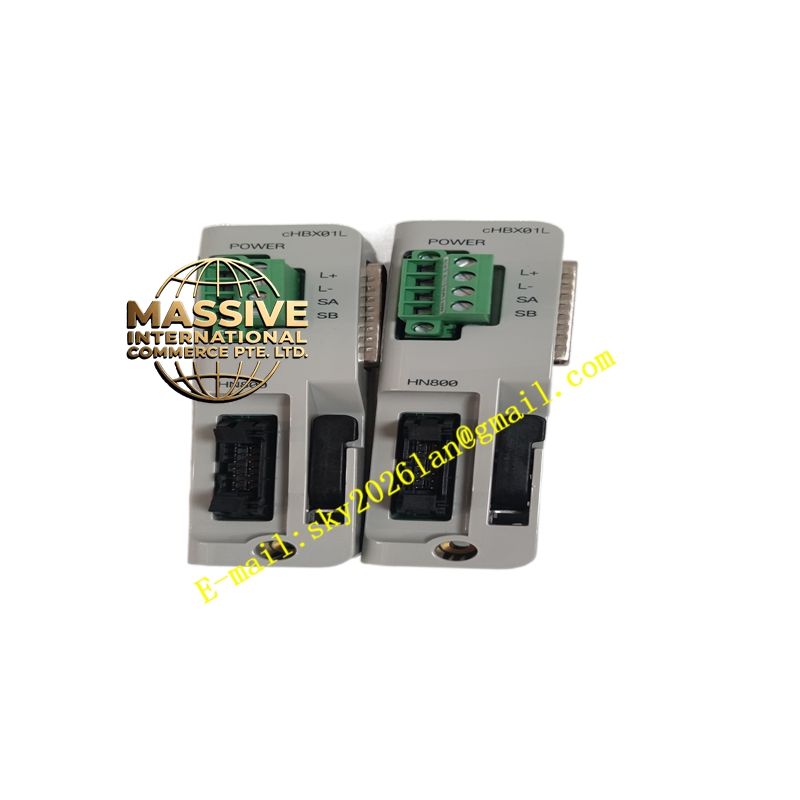
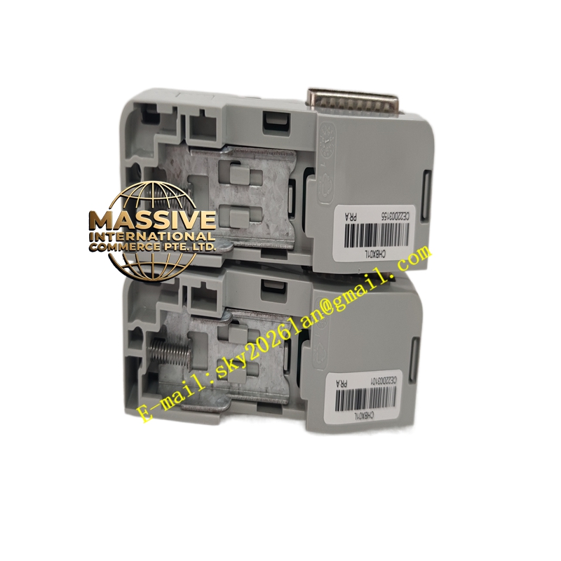
Description
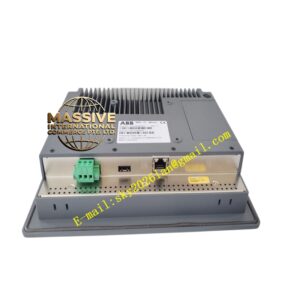
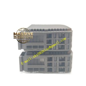
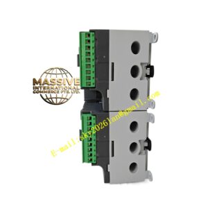
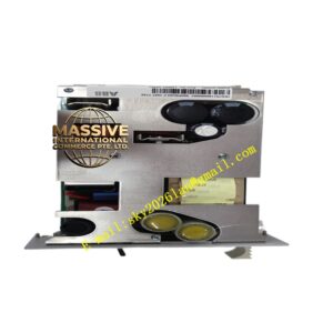
ABB CRBX01 (cRBX01)
- Technical Specifications:
- Function: HN800 bus optical repeater / media converter (electrical↔optical)
- Bus Supported: HN800 I/O bus (Symphony Plus SD Series I/O)
- Fiber Interface: 2 × ST-type connectors (62.5/125 µm multimode fiber standard)
- Max Fiber Distance: Up to 3 km (multi-mode, 62.5/125 µm, 850 nm wavelength)
- Capacity: Supports up to 60 HN800 devices per remote link; up to 8 remote links per controller (system dependent)
- Redundancy: Supports redundant HN800 bus (A/B) — two cRBX01 modules typically used per link for A/B redundancy
- Power: 24 V DC from base (VMU610 / RMU610), typical 90–100 mA
- Operating Temp.: –40 °C to +70 °C
- Mounting: Snaps onto VMU610 base (vertical DIN column) or horizontal DIN rail with adapter
- Diagnostics: Link/Activity LEDs per port; mini-USB for diagnostics on some versions
- Functional Features:
- Transparent signal regeneration — no addressing or node configuration
- Electrical isolation between controller segment and remote segment via fiber
- Hot-swappable when mounted in redundant pair or with power maintained on base
- Immune to EMI/ground loops — ideal for cross-building or high-noise environments
- Application Scenarios:
- Extending I/O bus from central control room to remote pump house / turbine island (>30 m, up to 3 km)
- Separating ground domains between process unit and I/O skid
- Power plant retrofits where old cable trays cannot accommodate new copper bus cabling
- Marine / offshore — noise immunity critical
- Material & Structure:
- Module: Flame-retardant ABS/PC housing, metal shield plate
- Base (VMU610): Aluminum DIN-rail mount with screw terminals for 24 V DC
- Fiber ports: ST (bayonet) style; dust caps supplied
- Working Principle:
The cRBX01 receives differential HN800 bus signals from the electrical side, converts them to optical pulses transmitted over fiber. The remote-end cRBX01 reconverts optical to electrical, reconstructing the timing and amplitude of the original signal. This regenerates the bus physically, allowing the remote I/O to appear logically as if locally connected.
- Installation Requirements:
- Mount cRBX01 on VMU610 base; secure base to 35 mm DIN rail in cabinet
- Connect 24 V DC to base terminals observing polarity
- Use 62.5/125 µm multimode fiber with ST connectors; clean fiber end-face before mating
- Connect one cRBX01 per HN800 bus (A and B) for redundant configuration
- Precautions:
- Do NOT look directly into fiber optic emitter — invisible 850 nm IR light can damage retina
- Verify fiber type and connector polish (prefer PC/UPO polish) — poor mating causes high loss
- Ensure both ends of the link are powered before expecting communication — dark fiber shows no link LED
- Maximum distance depends on fiber attenuation — verify with OTDR if close to 3 km limit