Description
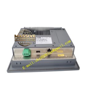
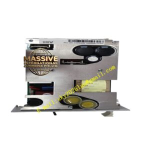
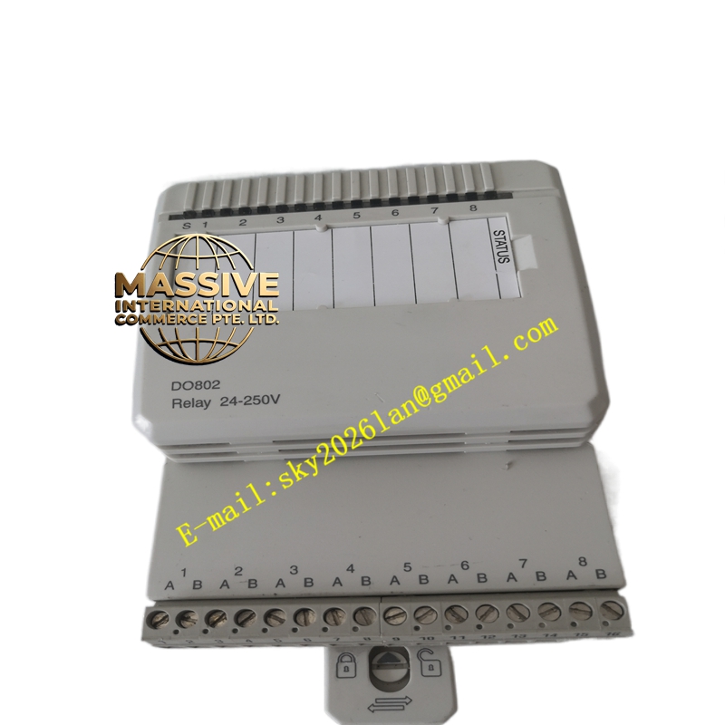
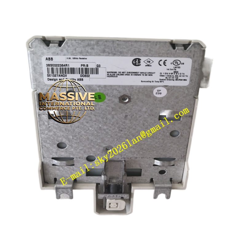
ABB DO802
- Technical Specifications:
- Output Type: Electromechanical relay, SPST-NO (Form A)
- Channels: 8, each channel fully isolated from others and from ModuleBus
- Rated Switching Voltage: Max 250 V AC, max 110 V DC (some versions 125 V DC — verify label)
- Rated Switching Current: 2 A resistive @ 250 V AC / 110 V DC; cos φ > 0.4 for AC
- Minimum Applicable Load: 10 mA / 5 V DC (contact wetting requirement)
- Contact Material: Silver alloy (AgCdO or AgSnO₂)
- Operate / Release Time: Typ. 10 ms / 5 ms
- Mechanical Life: >10 million operations (no load); electrical life ≈100,000 ops @ rated resistive
- Isolation Voltage: 2000 V AC channel-to-channel and channel-to-coil
- Relay Coil Supply Supervision: Monitors 24 V on ModuleBus; warning if lost
- Power Dissipation: Typ. 2.2 W (all relays energized)
- ModuleBus Current: +5 V typ. 70 mA; +24 V typ. 80 mA
- Max Field Cable Length: 600 m
- Operating Temp.: 0 °C to +55 °C
- Dimensions: 86.1 mm (W) × 110 mm (H) × 58.5 mm (D); weight ≈0.24 kg
- MTU: Dedicated S800L terminal unit
- Certifications: CE, UL/cUL, ATEX Zone 2, marine
- Functional Features:
- Full isolation between each relay channel — allows mixing AC/DC loads safely
- Relay coil voltage supervision with diagnostic reporting
- Per-channel status LED (yellow = relay energized)
- Varistor (MOV) across coil for spike suppression
- Suitable for switching lamps, solenoid valves (AC), motor starter coils, alarm horns
- Application Scenarios:
- Switching 230 V AC alarm sirens / beacons in plant annunciator systems
- Controlling 110 V DC / 230 V AC motor starter coils (interposing relay function)
- Mixed-voltage loads in one I/O station (one channel 24 V DC, another 230 V AC — fully isolated)
- Legacy equipment interfacing where dry-contact closure is required
- Material & Structure:
- Housing: Flame-retardant polycarbonate (S800L wider format)
- Relays: Plug-in style with silver alloy contacts; replaceable in some S800L designs (check version)
- Terminals: Screw type on S800L TU
- Working Principle:
The module receives a ‘1’ in the output image for a given channel; an opto-isolator triggers the relay-driver transistor which energizes the relay coil from the 24 V ModuleBus supply. The NO contact closes, connecting the field load to its supply. Loss of 24 V ModuleBus or communication error is detected and reported; the module can be configured to leave relays in last state or de-energize on comm loss.
- Installation Requirements:
- Mount in designated S800L terminal unit on 35 mm DIN rail
- Wire load between COM and NO terminal of each channel; observe voltage/current ratings
- For inductive AC loads (contactors, relays), fit external RC snubber or use contact-protected version to extend contact life
- Verify relay coil supply (24 V ModuleBus) is present before expecting output operation
- Precautions:
- Do NOT exceed 2 A resistive or specified VA rating — contact welding may occur
- Minimum load: very low current (<10 mA) may cause contact oxidation (“dry circuit” issue) — for very small signals use solid-state DO
- Relay click is audible — consider in quiet environments
- Replace relay at end of electrical life; verify correct replacement part number matches voltage/current rating
- Do NOT switch 230 V AC and 110 V DC on same channel simultaneously — follow nameplate limits