Description
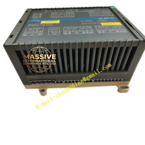
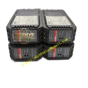
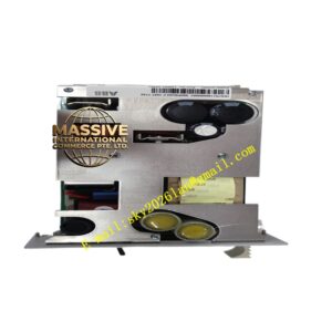
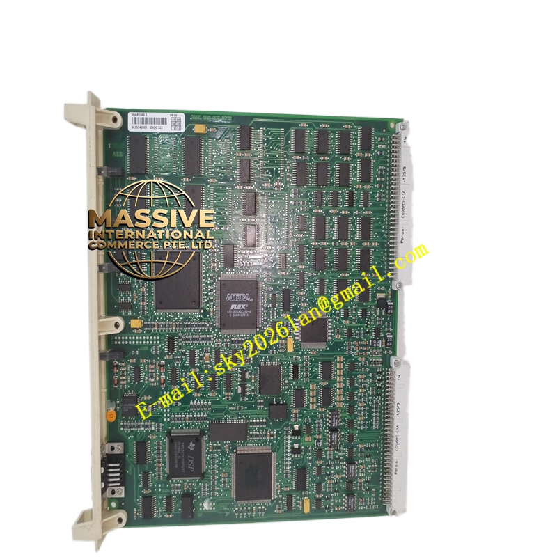
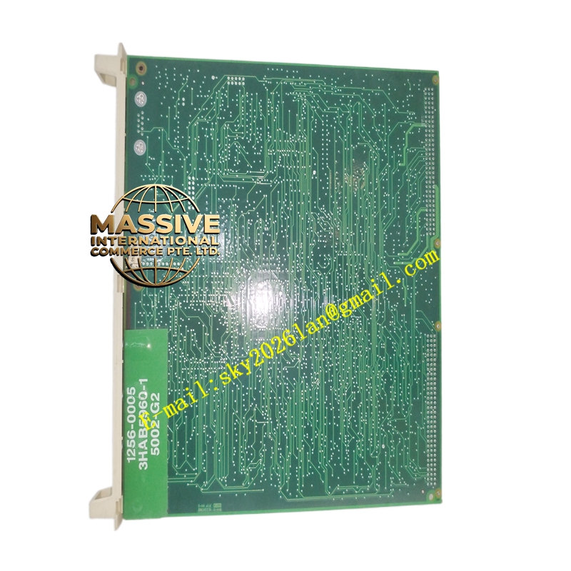
ABB DSQC322
- Technical Specifications:
- Digital Inputs: 16 channels, 24 V DC (18–30 V), typ. 7 mA/channel; accepts PNP or NPN (wired accordingly)
- Input Threshold: LOW ≤5 V, HIGH ≥11 V; software filter 0–32 ms
- Digital Outputs: 16 channels, 24 V DC high-side MOSFET, sourcing (PNP); 0.5 A max/channel, total ≤8 A per module
- Output Protection: Short-circuit and over-temperature protected, auto-recovery
- Supply Voltage: 24 V DC ±10 % (from robot controller internal supply or external UP)
- Power Consumption: Typ. 3 W (loaded)
- Interface: Connected via DSQC termination board (DSQC652 TB or equivalent) — 50-pin header to D-sub / screw terminal
- Bus: ABB DSQC internal bus (DeviceNet derivative, auto-addressed by controller)
- Indicators: Per-channel LEDs (Input green, Output yellow) + module status LED
- Operating Temp.: 0 °C to +55 °C; Storage –40 °C to +70 °C
- Humidity: 5–95 % RH non-condensing
- Mounting: PCB mounts inside IRC5 controller cabinet on dedicated DSQC I/O bracket or in separate I/O box
- Certifications: CE, UL, cUL, RoHS
- Functional Features:
- Direct mapping to RAPID program variables (DI / DO signals)
- Configurable input debounce filtering per channel group
- Output freeze / predefined state on communication loss (configurable in IRC5)
- Hot-swap capable when system configured for it (requires controller FW support)
- Diagnostic LEDs for rapid troubleshooting without FlexPendant
- Application Scenarios:
- Gripper open/close confirmation (input) and actuation (output) on IRB 120 / IRB 2600 / IRB 6640
- Fixture clamp / part-present sensor monitoring
- Start / stop command to small 24 V DC conveyors via interposing relay
- Safety gate monitored input, tower light output
- Material & Structure:
- PCB: FR4 with conformal coating option; gold-finger backplane connector
- Mounting: Metal standoff bracket or plastic guide rail inside IRC5 cabinet
- External connection via DSQC651/652 termination board (screw or D-sub)
- Working Principle:
The DSQC322 is addressed automatically by the IRC5 controller at boot. Digital inputs are read cyclically and placed in the controller’s I/O image; RAPID instructions read these as DI[n]. Output image bits from RAPID (DO[n]) are written to the MOSFET drivers each scan cycle. The module performs self-diagnostics and reports bus errors or output faults to the controller.
- Installation Requirements:
- Power down IRC5 controller before installing/removing DSQC board
- Seat DSQC322 firmly onto the DSQC I/O backplane or termination board header
- Connect field wiring via DSQC652 termination unit observing PNP (sourcing) or NPN (sinking) convention
- In RobotStudio / IRC5 configuration, add “DSQC322” to the Unit Type and assign starting signal addresses
- Reboot controller; verify module Status LED green
- Precautions:
- Do NOT exceed 0.5 A per output channel; use interposing relay for solenoid valves >0.5 A coil current
- Ensure external 24 V DC process supply (if used for outputs) shares 0 V reference with controller 0 V
- For safety-related signals (E-Stop, guard monitoring), use dedicated safety interface — DSQC322 is standard (non-safety) I/O
- Handle by PCB edges; use ESD wrist strap when installing