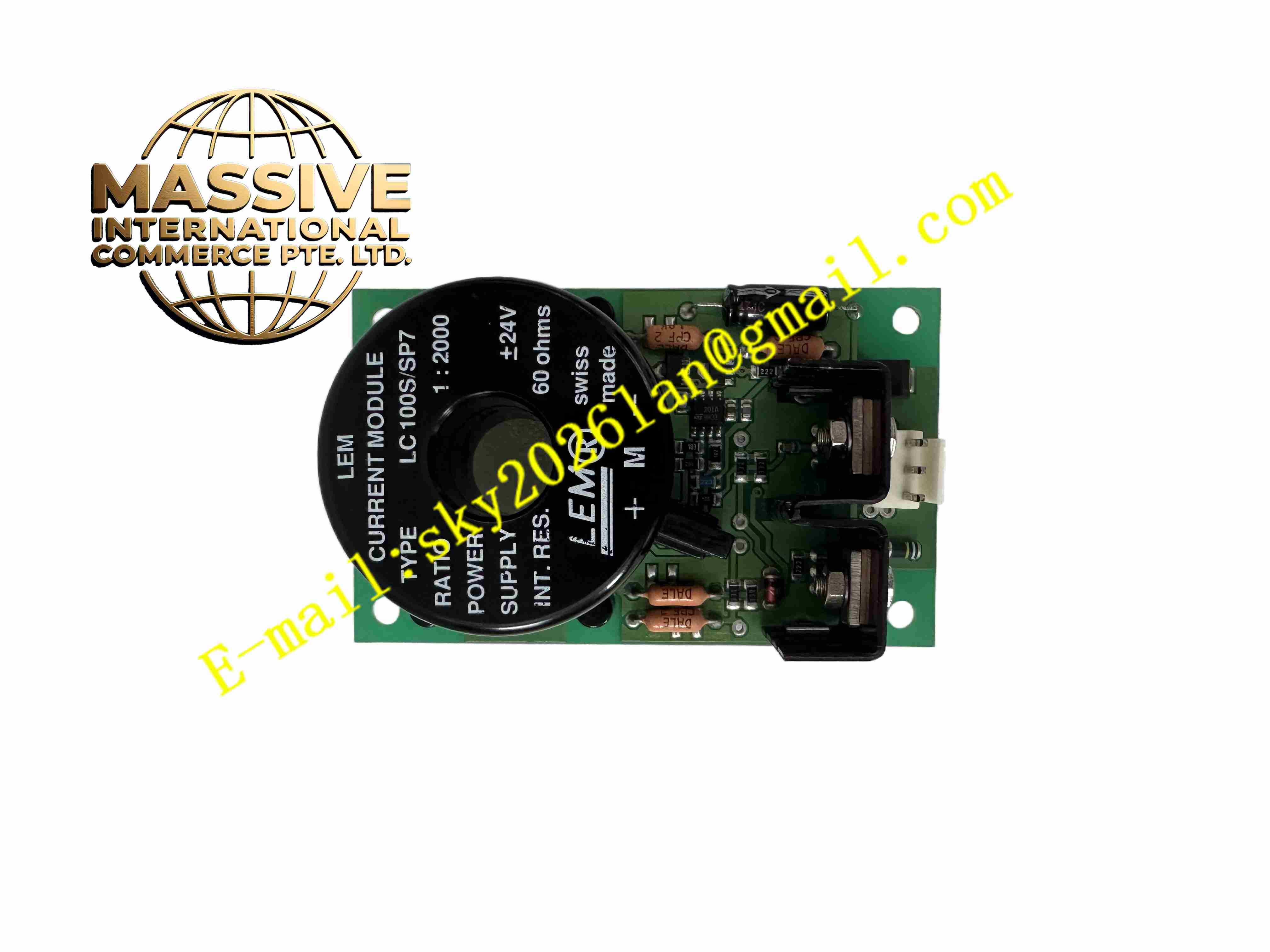
Description
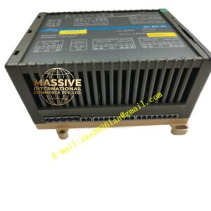
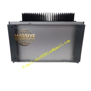
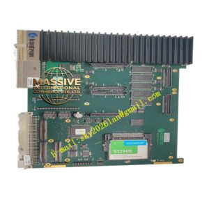
ABB LC100SSP7
Technical Specifications
- Product type: Low-voltage protection and measurement relay
- Measurement: Current, voltage, power, frequency
- Protection: Overcurrent, instantaneous, earth fault, undervoltage, overvoltage
- Control output: Relay contacts
- Communication: Modbus RTU RS485
- Supply: AC/DC100 to 240 V
- CT input: 5 A/1 A
- Temperature: -25 °C to +70 °C
- Storage: -40 °C to +85 °C
- Humidity: 5 % to 95 %, non-condensing
- Protection: IP20
- Installation: DIN rail
- Certifications: CE, UL
Functional Features
- Integrated motor, transformer, and capacitor protection
- Overcurrent, instantaneous, earth fault, undervoltage, overvoltage
- Current, voltage, power measurement display
- Relay contacts for trip/close and alarm
- Modbus RTU to background
- Local LCD and pushbutton operation
- Local or remote setting changes
- Event logging and fault recording
- DIN rail mounting
- Wide-temperature industrial design
Application Scenarios
- Low-voltage motor protection and measurement
- Low-voltage incoming and feeder protection
- Capacitor bank protection
- Low-voltage transformer temperature and protection
- MCC monitoring
Materials and Construction
- Housing: Flame-retardant engineering plastic
- Front panel: LCD and pushbuttons
- PCB: FR4 board
- Relays: Industrial electromagnetic relays
- Supply: AC/DC switching power supply
- Terminals: Screw-fastened terminals
Structural Features
- DIN rail square housing
- Front panel LCD, pushbuttons, LEDs
- Bottom CT, PT, control, and communication terminals
- Internal circuit partitions
- Removable terminal block
- Fanless natural convection
Working Principle CT secondary current and PT secondary voltage enter measurement circuits; sampling calculates current, voltage, power, and frequency. The protection CPU compares measured values to settings; on violation it triggers protection logic and outputs relay contacts to trip the breaker. The LCD shows live values and events. Modbus uploads data to background. Pushbuttons locally view measurements and modify settings.
Installation Requirements
- Snap-mount on 35 mm DIN rail
- Connect CT secondary wires by phase
- Connect PT voltage circuit
- Connect control output to breaker trip/close
- Shielded RS485 communication wire
- Supply AC/DC100 to 240 V
- Temperature -25 °C to +70 °C
Precautions
- CT secondary must not open-circuit
- Settings match motor rated parameters
- Verify CT ratio before power-up
- Correct RS485 A/B polarity
- Store spares in dry environment
- Periodically test protection operation