Description
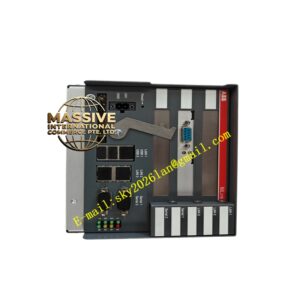
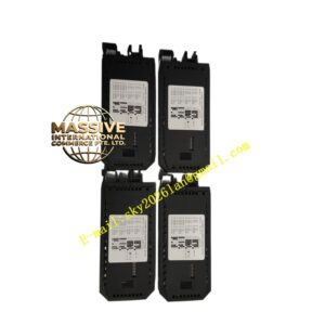
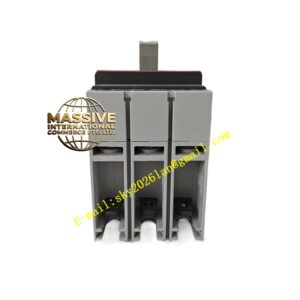
ABB NBRA669C
Technical Specifications:
- Applicable Systems: ABB ACS800/ACS880 series industrial drives.
- DC Bus Voltage: Compatible with 400V or 690V class drive systems.
- Braking Power: Provides corresponding peak and continuous braking power based on the matched braking resistor specifications.
Functional Features:
- Rapid Response: Continuously monitors DC bus voltage and instantly activates the braking circuit when the threshold is exceeded.
- High Duty Cycle: Supports high-frequency PWM chopping, ensuring a smooth and shock-free braking process.
- Comprehensive Protection: Built-in monitoring for braking resistor overheating, short circuits, and IGBT faults.
Application Scenarios:
Centrifuges, hoists, cranes, test benches, and conveyor lines requiring frequent emergency stops.
Performance Parameters:
- Switching Frequency: High-frequency IGBT chopping reduces thermal stress on the resistor and electromagnetic noise.
- Braking Torque: Capable of providing up to 100% or more continuous braking torque.
Material Composition:
Internally utilizes high-power IGBT modules and high-frequency diodes, equipped with high-efficiency heat sinks. The enclosure is made of metal or high-strength insulating materials.
Structural Features:
Modular design allows direct installation in the dedicated expansion slot of the drive or independent mounting in the control cabinet. Features braking resistor terminals and status indicators.
Working Principle:
By detecting the drive’s DC bus voltage, when the voltage rises to a set threshold, it controls the internal IGBT to conduct via PWM, connecting the DC bus to the braking resistor to dissipate regenerative energy and maintain the bus voltage within a safe range.
Installation Requirements:
Braking resistor cables must be connected strictly according to the manual, with cable length and cross-sectional area complying with specifications. The braking resistor must be installed in a well-ventilated area away from flammable materials.
Usage Precautions:
Never force-enable the braking function without a braking resistor connected or if the resistor circuit is open. Regularly inspect the braking resistor’s resistance value and terminal connections for looseness or burn marks caused by high temperatures.