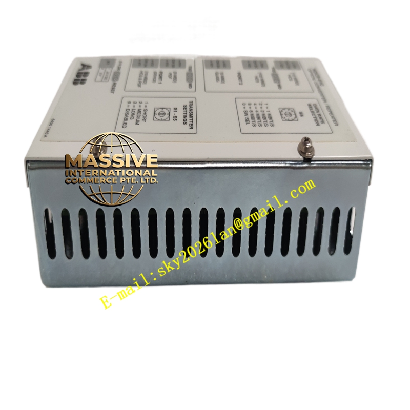
Description
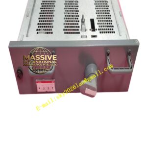
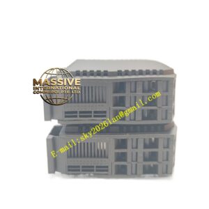
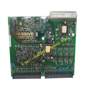
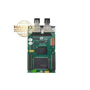
ABB NOCR-01C (3AFE64300245)
Technical Specifications:
- Output Type: Electromechanical relays (Form C / SPDT).
- Contact Rating: Typically 2A at 250V AC or 30V DC (resistive load).
- Number of Channels: Multiple independent relay outputs per module.
- Electrical Isolation: Full galvanic isolation between relay contacts and the internal module bus.
- Mechanical Life: High-cycle rated relays for extended operational lifespan.
Functional Features:
- Versatile Switching: Capable of switching both AC and DC loads without polarity concerns.
- Status Indication: Front-panel LEDs provide immediate visual confirmation of each relay’s energized state.
- Fault Detection: Integrated diagnostics to detect open coil or shorted contact conditions.
- Hot-Swappable: Designed for replacement while the controller remains powered and operational.
Application Scenarios:
- Alarm annunciation and beacon control in industrial plants.
- Actuation of pneumatic and hydraulic solenoid valves.
- Motor starter and contactor coil control.
- Safety interlock signaling and permissive outputs.
Performance Parameters:
- Response Time: Fast relay actuation and release times for precise control.
- Inrush Current: Rated to withstand high inrush currents typical of lamp and motor loads.
- Contact Resistance: Low and stable contact resistance for minimal voltage drop.
- Dielectric Strength: High isolation voltage to protect the controller from field transients.
Material Composition & Structural Characteristics:
- Relays: High-quality industrial relays with silver-alloy contacts for arc resistance.
- Enclosure: Rugged plastic housing with integrated DIN rail mounting.
- Terminals: Removable screw terminal blocks for fast and secure field wiring.
- PCB: Heavy copper traces on the PCB to handle relay coil and contact currents safely.
Working Principle:
When the AC800M controller executes a logic rung that energizes a specific output variable, the signal is routed to the NOCR-01C module. The module’s driver circuit energizes the relay coil, creating a magnetic field that mechanically closes the contact. This completes the external load circuit. When the logic de-energizes the output, the coil releases, and a spring returns the contact to its resting position.
Installation Requirements:
- Load Wiring: Connect field loads to the Common (C), Normally Open (NO), and Normally Closed (NC) terminals as required by the application.
- Wire Sizing: Use appropriately sized wire to handle the maximum load current without excessive voltage drop.
- Inductive Loads: Install snubber circuits or flyback diodes across inductive loads to protect relay contacts from arcing.
- Power Supply: Ensure the external load power supply is correctly rated and fused.
Usage Precautions:
- Load Limits: Never exceed the maximum voltage, current, or power ratings specified for the relay contacts.
- Contact Life: Be aware of the mechanical and electrical life limits; high-frequency switching applications require solid-state output modules.
- ESD Safety: Handle the module with ESD precautions to prevent damage to the internal driver circuitry.
- Maintenance: Periodically inspect contacts for pitting or welding if switching heavy inductive loads.