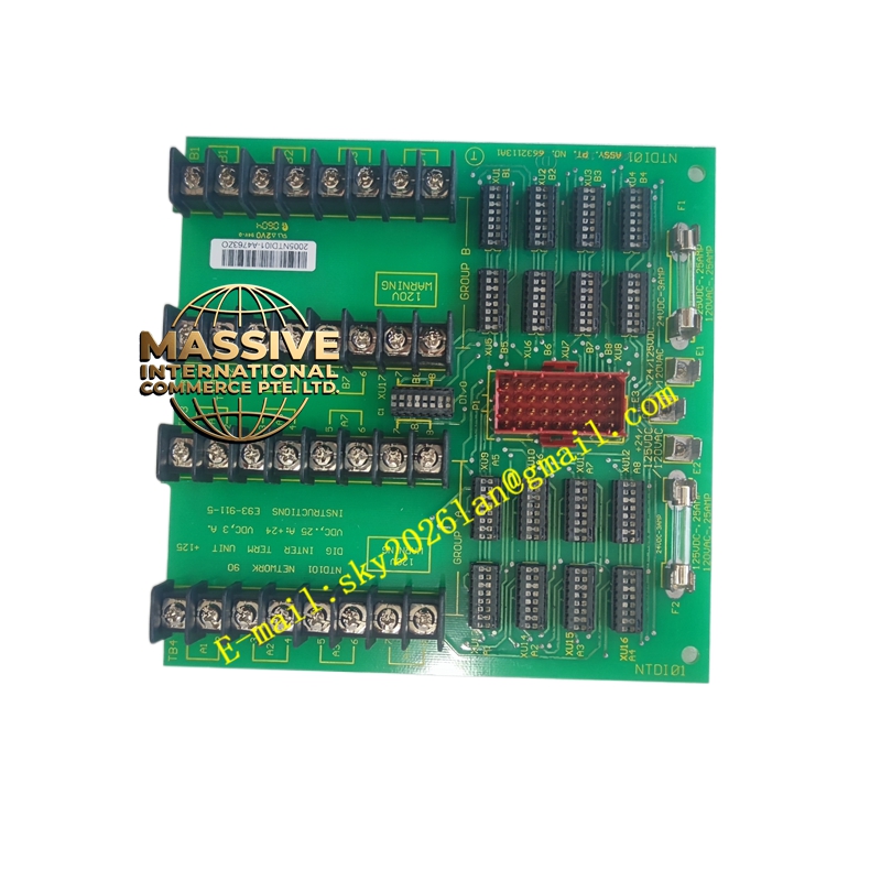
Description
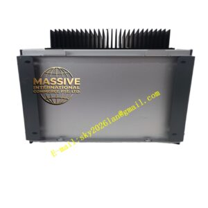
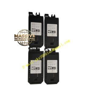
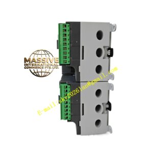
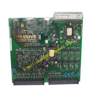
ABB NTDI21-A
- Technical Specifications (typical 24 V DC version — verify grade by module label):
- Input Channels: 16 (single group) or 32 (2 groups × 16) — NTDI21 is commonly 16 ch; 32-ch exists in later Harmony
- Input Voltage Grade: Module-specific — NOT mixable
- 24 V DC: 18–30 V; threshold ON ≥11 V, OFF ≤5 V; typ. 7 mA per ch
- 48 V DC: 38–60 V
- 110 V DC: 88–132 V; typ. 2–3 mA
- 220 V DC: 176–253 V; typ. 1–2 mA
- 230 V AC ±10 % 50/60 Hz (some versions)
- Response Time: <10 ms typical; software debounce filter 0–127 ms (does NOT affect SOE time stamp — first valid edge tagged)
- SOE Capability: Available on some NTDI21 / IMFEC12 pair — NTDI21 itself may report basic DI; for SOE use IMFEC12; some late-rev NTDI21-A with SOE flag in ID PROM works with SOE server
- Isolation: 1500 V AC channel-group-to-backplane; channel-to-channel share common reference within group
- Module Power: 5 V DC from backplane (typ. 150 mA for 16-ch; 250 mA for 32-ch)
- Indicators: Run (green), Fault (red), C.W. Active (green); per-group Input Active LED (illuminates when any channel in group = ON)
- Operating Temp.: 0 °C to +60 °C
- Dimensions: Single-slot INFI 92 module (≈30 mm W)
- Functional Features:
- Wetting voltage provided internally for dry contacts (module sources limited current to sense closure)
- Compatible with N.O. or N.C. wiring — logic inversion done in software parameter
- Reports module diagnostics (backplane power loss, config mismatch) to controller
- High-voltage grades allow direct connection to utility-grade breaker aux contacts, protection relay contacts (110/220 V DC) without interposing relay
- Works with redundant C.W. bus and hot-swap (when rack configured for it)
- Application Scenarios:
- Limit switch / position switch monitoring (N.C. for guard doors, N.O. for “in position”)
- Breaker / disconnect switch auxiliary contact status in electrical substations (110/220 V DC versions)
- Pushbutton / selector switch status on local panels
- Pump “Running” / “Fault” feedback from MCC aux contacts (24 V DC or 110 V DC per MCC design)
- Material & Structure:
- Housing: Flame-retardant ABS/PC with transparent status window
- PCB: Industrial FR4, G3 conformal coat on process-grade versions
- Edge Connector: 30-pin gold-plated for IEMMU21 backplane
- Keying: Physical key on module bottom engages coded IEMMU21 slot (key set for DI module type)
- Working Principle:
When a field contact closes, the module’s internal opto-coupler is forward-biased by the grade voltage (e.g., 24 V DC through current-limiting resistor → opto-LED → contact → common). The opto-transistor saturates, pulling the channel bit LOW (or HIGH depending on polarity convention) in the module’s input latch. The C.W. scan reads the latch contents and places them in the controller’s I/O image table. Open contacts leave the opto off → bit = opposite state. Debounce filtering rejects contact bounce < filter setting.
- Installation Requirements:
- Insert NTDI21-A into available I/O slot (Slots 2–10 typically; Slot 1 = controller/comm) of IEMMU21 — align key
- Wire field contact between input terminal (I0…I15) and common (Cx) on the associated Termination Assembly (TA):
- 24 V version: TA567 (low voltage); 110/220 V version: TA568 or TA569 (high voltage — finger-safe!)
- For dry contacts: module provides sense voltage — simply close contact between Ix and Cx
- In INFI 92 Configurator: assign module type = , set voltage grade (auto-read from module ID PROM), debounce time, normal state (N.O./N.C.)
- Power up rack; verify Run LED green; check channel LEDs operate when contact closed
- Precautions:
- — immediate destruction of input circuitry
- For 110/220 V DC versions: ensure proper clearance, use finger-safe terminal covers — hazardous voltage present even when logic de-energized
- Verify common (Cx) wiring — all channels in a group share one common reference; do NOT mix PNP sensor outputs with voltage-grade DI unless externally referenced correctly
- Use shielded cable for long runs in noisy environment; ground shield at one end (cabinet earth)
- If using for SOE: confirm module revision & controller config actually support SOE — otherwise use IMFEC12 for guaranteed 1 ms SOE