Description
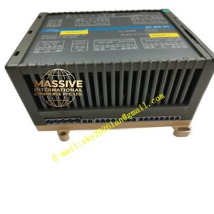
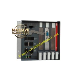
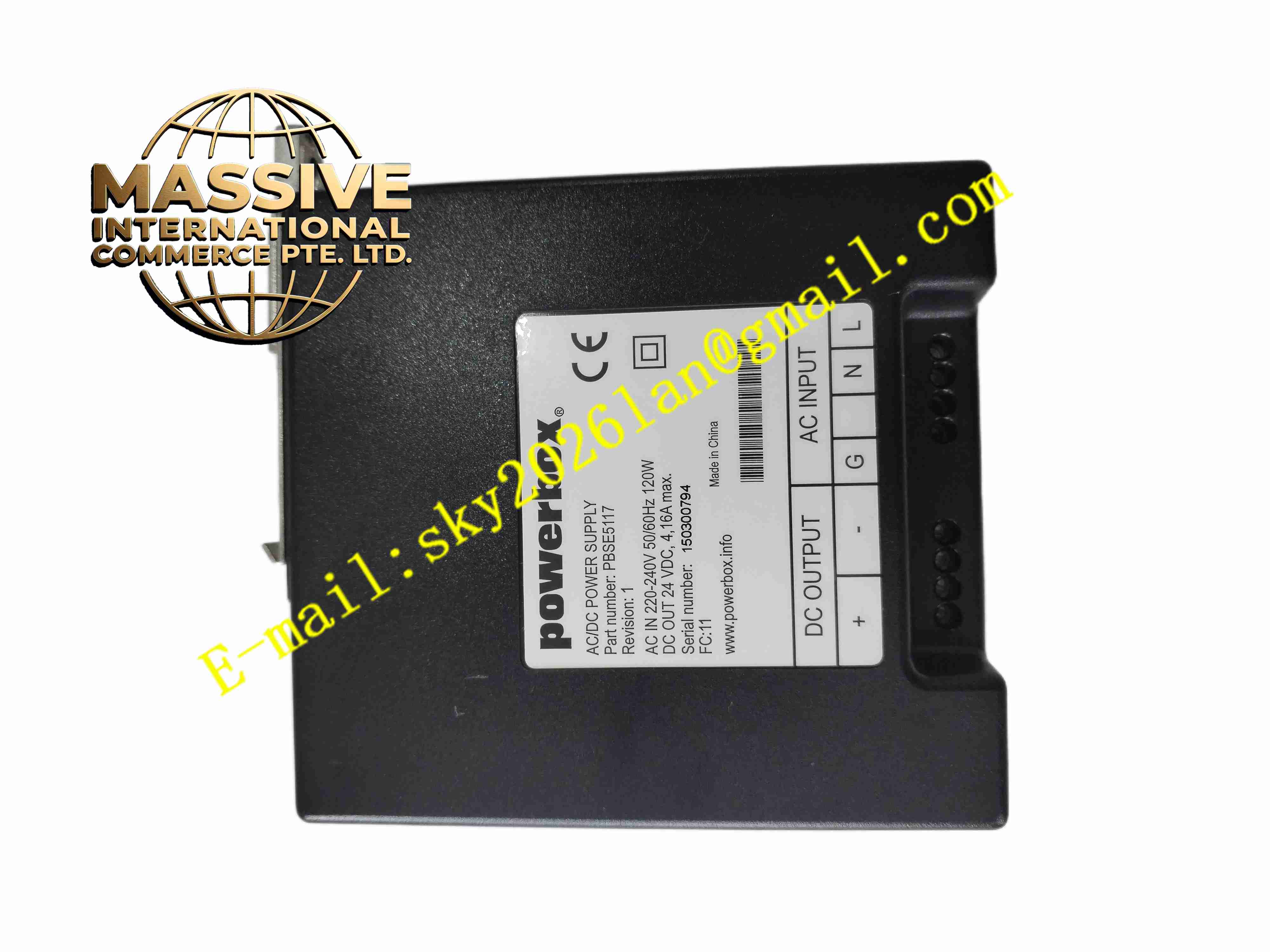
ABB PBSE5117
Technical Specifications: Product type: Substation bay control binary I/O interface board Binary input: Multi-channel isolated digital input for auxiliary contact status Binary output: Relay contact output for breaker control and interlock Backplane interface: ABB proprietary control system backplane bus Board power supply: Supplied from bay control chassis backplane Operating temperature range: -10℃ ~ +60℃ Storage temperature range: -40℃ ~ +85℃ Relative humidity: 5% to 95%, non-condensing Form factor: Rack plug-in module board Protection grade: IP20 when installed inside control cabinet
Functional Features: Multi-channel isolated binary input to collect switchgear auxiliary contact status. Relay contact binary output for circuit breaker close, trip and interlock command. Galvanic isolation between field wiring circuit and internal control backplane circuit. Surge and transient overvoltage suppression for field signal wiring. Continuously monitor input contact state and transmit status data to main controller. Execute hardware interlock logic for switchgear operation permission. Front panel LED indicators for each channel input status and output operation. Hardware self-diagnosis for board power and internal circuit fault.
Application Scenarios: High voltage substation bay control cabinet, power plant generator switchgear control, distribution substation switch interlock system, railway traction substation bay control, hydroelectric power plant switchgear monitoring and control.
Performance Parameters: Fast binary input state capture for switchgear contact change. Relay contact meets substation control circuit load requirement. Isolation circuit withstand transient surge from substation field wiring. Continuous operation: 24 hours uninterrupted operation in substation control cabinet. High immunity to substation strong electromagnetic interference.
Material Composition: PCB substrate: Multi-layer FR4 glass fiber epoxy printed circuit board with conformal coating. Core components: Optocoupler isolation chip, digital logic IC, electromagnetic relay, surge suppression diode array, backplane communication chip. Front panel: Black flame retardant ABS plastic panel with silk screen and LED transparent windows. Backplane connector: Gold plated copper alloy contact pins. Field terminal block: PA66 flame retardant plastic screw terminal block with tinned copper contacts.
Structural Features: Single slot plug-in rectangular board structure matching ABB control rack. Front panel with LED indicators corresponding to each binary input and output channel. Internal circuit layout separated into field signal isolation area, logic processing area and backplane bus interface area. Independent optocoupler isolation for each binary input channel. Electromechanical relay for binary output control. Mechanical locking latch to fasten board inside rack slot. Rear side terminal block for field switchgear wiring connection.
Working Principle: Board receives low voltage DC power supply from bay control chassis backplane. Binary status signal from switchgear auxiliary contact enters board through field terminal block. Optocoupler isolates field signal and converts contact state into digital logic signal for on-board logic circuit. Logic circuit communicates with main controller via backplane bus. When main controller sends close or trip command, corresponding relay coil energizes and relay contact closes to output control signal to switchgear operating circuit. Surge suppression circuit absorbs transient overvoltage coming from field wiring. Board continuously monitors channel status, and LED indicators display input state and relay operation state.
Installation Requirements: Cut off bay control cabinet auxiliary power before inserting or removing PBSE5117 board. Insert board into designated rack slot and lock mechanical latch. Connect switchgear auxiliary contact wiring and breaker control circuit wiring to field terminal block. Configure binary input mapping and interlock logic in ABB bay control engineering software. Ensure cabinet protective earth ground connection is reliable. Separate field control cables from high voltage primary cables. Reserve air gap between adjacent rack modules for heat dissipation.
Usage Notes: Backup bay control configuration before board replacement. Check control circuit wiring polarity during commissioning. Wear anti-static wristband when handling board. Do not exceed rated relay contact load capacity. Regularly inspect terminal screw tightness and LED channel status. Do not operate board outside rated temperature and humidity range. Prevent conductive dust and moisture accumulation on terminal block and PCB surface.