Description
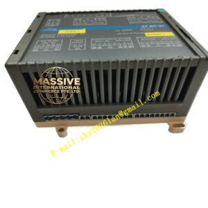
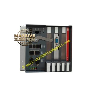
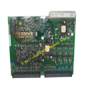
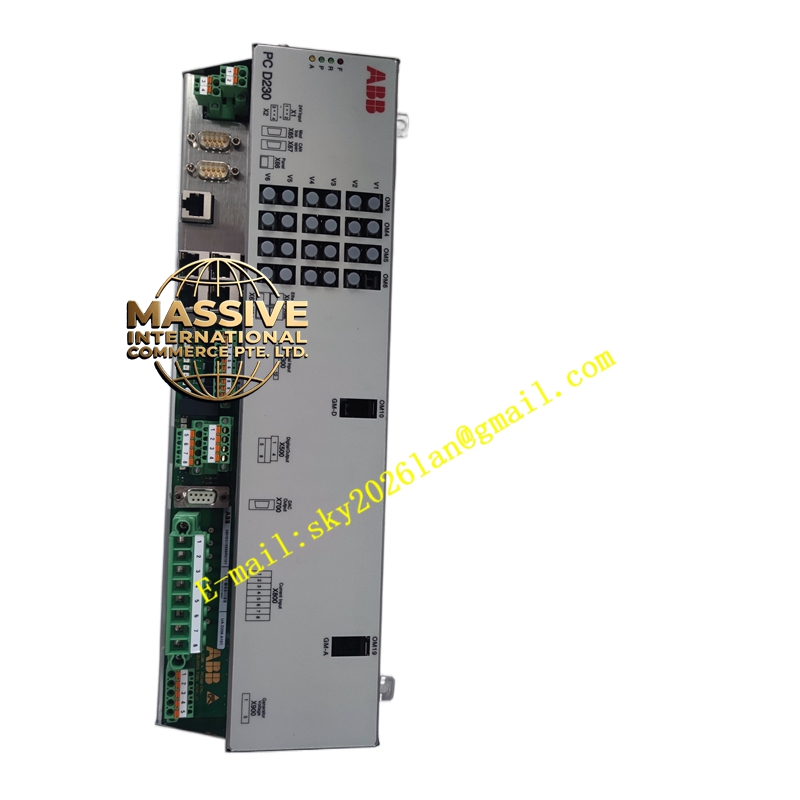
ABB PCD230A101
- Technical Specifications:
- Processor: 32-bit RISC + DSP; regulation cycle: current loop 100 µs, voltage loop 1 ms
- Inputs: Generator PT voltage (1–5 V or 100/√3 V via VT secondary), CT current, field voltage/current feedback, speed signal (optional)
- Outputs: Firing angle command → fiber to thyristor gate units; limit/alarm contacts (Form C relay)
- Communication: Ethernet 10/100 Mbps (Modbus TCP, IEC 61850-8-1 MMS/GOOSE optional), Profibus DP-V1, RS-232/485 for local HMI
- Fiber Ports: 100 Mbps to gate pulse unit(s); 100 Mbps to redundant PCD (if 1oo2)
- Supply: 24 V DC (18–32 V), typ. 150 W max with all I/O
- Diagnostics: Run, Sync, Fault, Com LEDs; internal event log with 1 ms time stamp; built-in oscilloscope (soft scope) for commissioning
- Operating Temp.: –20 °C to +60 °C
- Mounting: 19″ rack or DIN-rail sub-frame in excitation cubicle
- Dimensions (module only): ≈200 × 150 × 100 mm; in enclosed chassis larger
- Certifications: IEC 60255 (measuring relays), IEEE 421.5 compliant
- Functional Features:
- Auto / Manual transfer with bumpless tracking
- Built-in PSS2A/PSS4B, UEL (under-excitation limiter), OEL (over-excitation limiter with I²t thermal model), V/Hz limiter
- Low-Voltage Ride Through (LVRT) per grid code
- Dual-redundant PCD pair (1oo2) with automatic switchover on fault detection
- Local HMI port for commissioning (laptop / excitation touch panel)
- Supports reactive power control, PF control, MVAR setpoint in addition to terminal V control
- Application Scenarios:
- Unitrol 5000 static excitation system for generators 1 MW–1000 MW+
- Retrofit of older excitation cubicles (BBC / ABB legacy AVR → PCD230)
- Combined-cycle / cogeneration plant generator excitation
- Hydro generator excitation with PSS for grid stability
- Material & Structure / Working Principle / Installation / Precautions:
- Mount in excitation cubicle with adequate ventilation; connect 24 V DC aux supply (separate from thyristor power)
- Connect PT/VT and CT secondaries observing polarity and burden limits; connect fiber to GPU
- In excitation engineering tool: perform OLF (Open Loop Test) — manually step firing angle, observe field voltage response; then close loop
- Set limiters per generator capability curve (OEL I²t time constant from generator thermal capability; UEL min/excitation limit from stability study)
- Precautions:
- High-voltage PT/CT secondaries must be fused and correctly grounded per local code
- Never energize thyristor bridge firing circuits before verifying synchronization polarity
- Firmware version must match engineering tool version — mismatch prevents download
- For redundant pair: both PCD must be same firmware; cross-check after replacement
- Periodically verify limiter operation (OEL trip test during planned outage per SIS/Maintenance schedule)