Description
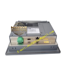
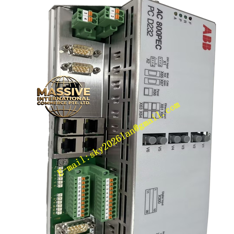
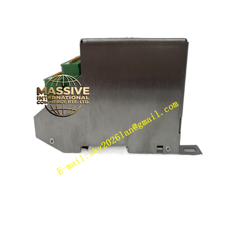
ABB PCD232A101
- Technical Specifications (similar to PCD230 but with integrated I/O):
- Processor / Regulation: Same 100 µs current loop, 1 ms voltage loop; PSS, UEL/OEL, V/Hz limiters
- Integrated Analog Inputs:
- 3 × VT inputs (phase-to-phase or phase-to-neutral, 100 V / 110 V / 120 V rms secondary — jumper selectable)
- 3 × CT inputs (1 A / 5 A selectable; burden ≤0.2 VA)
- Field Voltage & Field Current feedback (via shunt or DCCT — 60 mV / 4–20 mA)
- Integrated Digital I/O:
- Typically 8–12 DI (24 V DC) for: Field Breaker Aux, 86-Lockout contact, Manual/Auto select, Raise/Lower contacts, E-Stop
- 4–6 DO (relay or 24 V DC transistor) for: Alarm, Trip to field suppression contactor, Run/Ready LED drive
- Gate-Pulse Interface: 100 Mbps fiber to thyristor GPU (up to 6-pulse or 12-pulse bridge)
- Communication: Ethernet 10/100 Mbps (Modbus TCP, IEC 61850 optional), Profibus DP-V1, RS-232/485 for local service port
- Supply: 24 V DC (18–32 V), typ. 200 W max with all I/O excited
- Diagnostics: Built-in oscilloscope (soft scope), event log, LED bar graph for field current / terminal voltage
- Mounting: 19″ rack panel or DIN-rail sub-enclosure in excitation cubicle
- Operating Temp.: –20 °C to +60 °C
- Functional Features / Application / Material / Working Principle / Installation / Precautions: Same AVR principles as PCD230A101 — key difference is integrated I/O termination — no separate analog termination unit needed (though external PT/CT fuses & test switches still required in cubicle wiring). Commissioning steps identical: OLF → limiter setup → close loop → synchronize.
- Extra Precaution: Because I/O is onboard, verify jumper settings for VT (100 V vs 110 V vs 120 V) and CT (1 A vs 5 A) BEFORE energizing PT/CT secondaries — wrong jumper can saturate input circuits or give incorrect readings. Perform ratio check with secondary injection during commissioning.