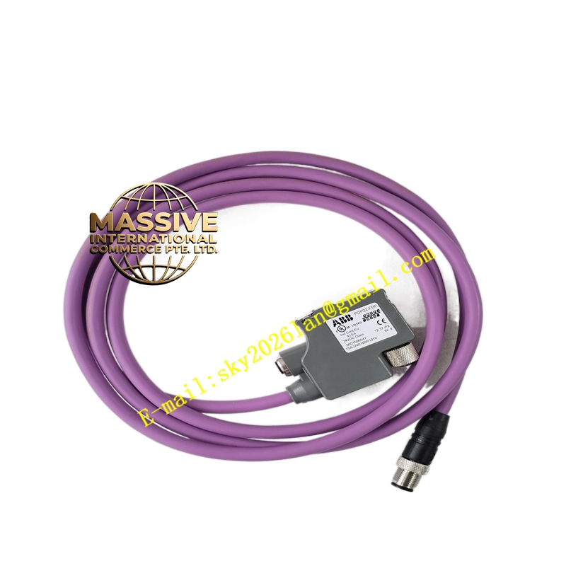
Description
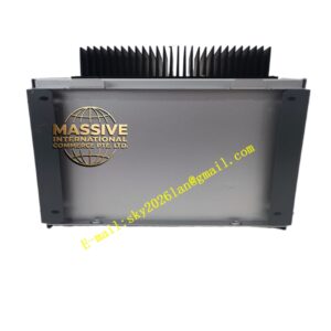
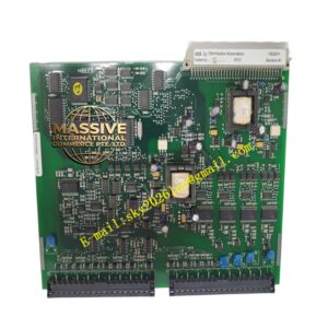
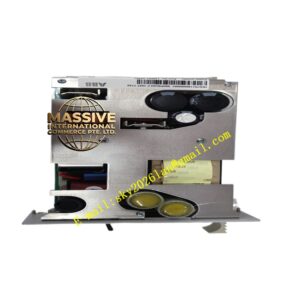
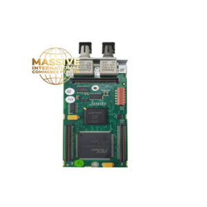
ABB PDP22-FBP
- Technical Specifications (typical LD800 / PDP22-FBP):
- H1 Ports: 1 or 2 × FF H1 (31.25 kbps); each supports up to 16 devices (max 32 per spec, recommended ≤16 for margin)
- H1 Power: Integrated Power Conditioner — 24 V DC input → regulated 24 V DC on H1 with 30–90 mA available for field devices (IS barrier version: MTL or Pepperl+FuchsIS barrier internal)
- Host Interface: PROFIBUS DP-V1 Slave (9-pin D-sub) or Ethernet 10/100 Mbps (Modbus TCP / FF HSE — model dependent)
- PROFIBUS DP Baud: 9.6 kbps – 12 Mbps auto; GSD file provided
- Function Block Support: Transparent — FF function blocks execute in field devices; linker passes data each macrocycle
- Alarms & Diagnostics: Device fail, segment short, power loss, comm error reported via host network; local LEDs (Power, Com, H1 Active, Fault)
- Power Supply Input: 100–240 V AC or 24 V DC (model dependent)
- Enclosure: IP20 (DIN-rail) or IP54 (wall-mount field enclosure for IS version)
- Operating Temp.: –20 °C to +60 °C
- Certifications: FM, CSA, ATEX (IS version: Ex ia IIC T4/T6), CE, IEC 61784-1/2
- Functional Features:
- Built-in FF power conditioner — no separate PC800 needed (in FBP combo unit)
- IS version allows direct connection to Zone 0/1 FF H1 devices (with appropriate entity parameter check)
- Redundant Linking Device pairs supported (some models)
- Time distribution to FF segment (via Link Active Scheduler — LAS function in linker)
- Device discovery & capability file (CFF) download via host engineering tool (ABB Control Builder / DeltaV/ other FF host)
- Application Scenarios:
- Integrate FF H1 field instruments (pressure, temperature, flow, valve positioners with FF) into ABB 800xA / Symphony Plus via PROFIBUS DP or Modbus TCP
- Retrofit of legacy analog I/O to FF — keep instruments, add linker to connect to modern DCS
- Oil & gas / chemical plant — multiple FF segments per process unit, each on its own PDP22-FBP H1 port
- Material & Structure / Working Principle / Installation / Precautions:
- DIN-rail mount in system cabinet (non-IS) or field junction box (IS version — purge/explosion-proof as required)
- Wire H1 segment to H1+ / H1– terminals; observe polarity; terminate both ends of H1 trunk with 100 Ω resistor (some linkers provide switchable internal termination — enable only on last device segment end, NOT on linker end usually)
- Connect host network (Profibus DP to CI854 or Ethernet to plant switch)
- In 800xA / S+ Engineering: import EDS/GSD, define linker as FF H1 host; assign devices & schedules
- Precautions:
- For IS version: verify Entity parameters (Uo, Io, Po, Co) of linker against field device Ex i certificate — must satisfy: Uo ≤ Umax_device, Io ≤ Imax_device, Po ≤ Pmax_device
- Do NOT connect AC power to 24 V DC input version — check nameplate
- H1 trunk shield must be grounded at ONE point (typically at linker end or at drain wire ground — follow FF installation guide: shield drain connected to ground at linker, insulated at field device end)
- Ensure total device current draw on H1 segment < available power conditioner current (typically 30–90 mA depending on model / cable length)