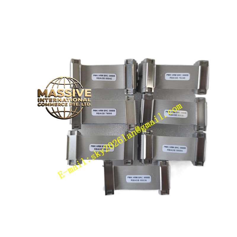
Description
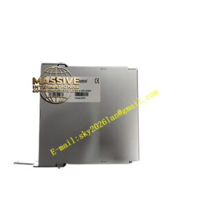
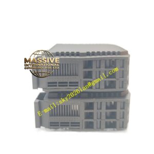
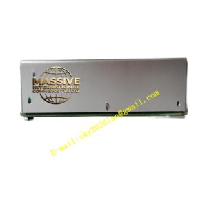
ABB PMKHRMBRC3000B
- Technical / Installation Details:
- Fits IEMMU21 Enhanced Module Mounting Unit — occupies Slots 1 & (optionally) 1A for redundant pair
- Material: Sheet steel, zinc-plated or painted gray (RAL 7035)
- Keying: Plastic key blocks insert into baseplate key slots — ensure key set to “Controller” position (per IEMMU21 key chart — usually code AA or AB for BRC)
- Sync Cable: Short flat ribbon (≈150 mm) connects two BRC-300 CPUs for hot-standby data sync — included in redundant kit
- Earth: Braided ground strap from carrier to rack chassis
- Application Scenarios:
- New INFI 92 rack build — install PMKHRMBRC3000B first, then insert BRC-300 CPUs
- Replacement of worn/damaged controller carrier in existing rack
- Converting single-controller rack to redundant pair (add second BRC + sync cable — may need this kit if original was single)
- Installation Steps:
- Power down rack; remove any existing module from Slot 1
- Snap PMKHRMBRC3000B carrier into Slot 1 guide rails; secure with screws
- Insert keying plugs per IEMMU21 key chart (match controller type)
- Insert BRC-300 CPU(s) into carrier; seat firmly; tighten retaining screw(s)
- If redundant: connect sync cable between two CPUs (marked P1↔P1)
- Connect NTMP01 memory module to each CPU before power-up
- Power up; verify Run / Sync LEDs
- Precautions:
- Verify key code BEFORE inserting CPU — wrong key prevents insertion or causes backplane mis-mating
- Handle sync cable gently — do NOT fold sharply; ensure both ends seated
- For redundant pair: both CPUs must be identical model & firmware; after first boot of primary, standby auto-syncs (SYNC LED green)