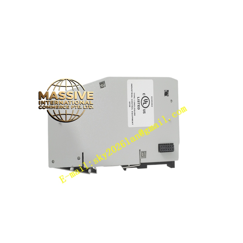
Description
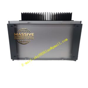
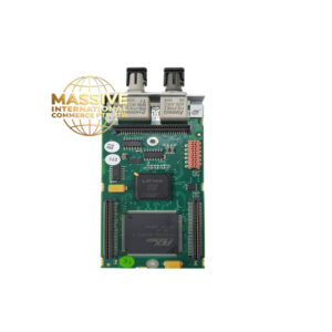
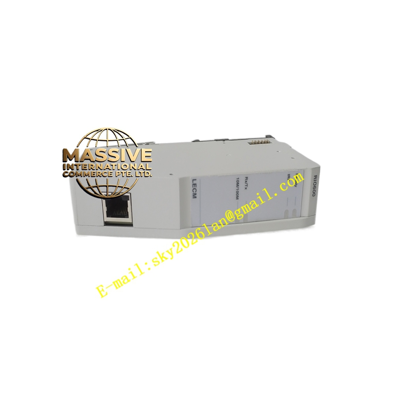
ABB RIO600
- Technical Specifications (typical S800 remote node):
- Max I/O Modules per Node: 12 (on single TB820 baseplate); up to 2 TBUs daisy-chained in some configs → 24 modules max per HN800 interface
- HN800 Bus: 100 Mbps HDLC-based; copper (CAT5e STP, max 100 m) or multimode fiber (max 2 km typical; single-mode 15+ km with media converter)
- Redundancy: HN800 A/B bus + optional redundant CI840A pair + redundant PSU (N+1)
- Module Power: 24 V DC input to PPD113A01; 5 V DC logic derived internally; UP (process 24 V) distributed to modules
- Diagnostics: Module missing, wire break (on DI/DO with supervision), open sensor (AI), short-circuit (DO) — all reported to controller
- Operating Temp.: 0 °C to +55 °C (S800 modules); –20 °C to +60 °C (CI840A)
- Mounting: 35 mm DIN rail in field J-box, local panel, or control cabinet
- Certifications: CE, UL, cUL, ATEX Zone 2 (with system cert), marine (DNV/ABS/LR)
- Functional Features / Application / Material / Structure / Working Principle / Installation / Precautions:
Same as S800 I/O system:
- Install TB820 baseplate + TU843/TU846 termination units on DIN rail
- Plug in I/O modules (DI830, DO820, AI835, AO845…) into TUs
- Install CI840A (or CI841 for Profibus DP gateway) into CEX slot on baseplate (or onto AC 800M if local — but RIO = remote so CI840A at remote end)
- Connect 24 V DC PSU to PPD113A01; wire UP distribution if DO/AI need process voltage
- Connect HN800 fiber/copper from controller side (or from previous RIO node) → CI840A port A; if redundant B bus → port B
- In Control Builder M / Freelance Eng Tool: define Remote I/O station → assign module types & addresses → download → verify Com LED on CI840A
- Precaution: Terminate HN800 bus at both ends with 120 Ω resistor (built-in jumper or external). Verify fiber polarity (Tx→Rx). For redundant PSU: diode-OR; size each PSU for full load + margin. After module replacement hot-swap is supported — ensure controller scan allows it (default = yes).