Description
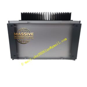
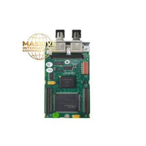
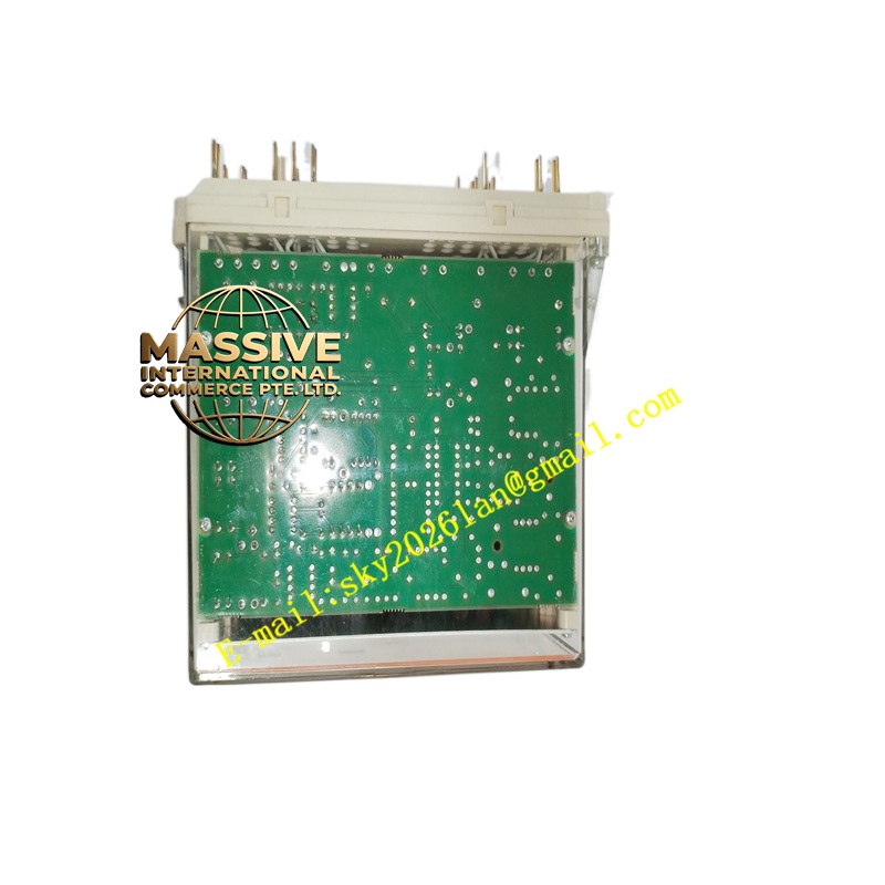
ABB RXDS4
- Technical Specifications (typical modern 3-phase test set — RXDS4 era or successor):
- Current Outputs: 3 × phase (0–100 A @ 250 VA max each; 0–300 A short-time for primary inj adapter), 1 × residual (0–10 A)
- Voltage Outputs: 3 × phase (0–4 × 250 V L-L @ 60 VA per phase; 0–150 V L-N)
- DC Outputs: ±10 V / ±20 mA (for transducer test)
- Binary Inputs: 4–8 (monitor relay contact closure — measure operate time)
- Timer Resolution: 0.1 ms
- Control: Local keypad + LCD or PC software (via USB / Ethernet)
- Memory: Store test plans (OC curve, diff slope sweep, zone reach pts)
- Power: 230 V AC 50/60 Hz (internal SMPS)
- Dimensions: Bench-top ≈450×150×350 mm; weight ≈12–18 kg
- Safety: CAT III 300 V (for secondary injection only — NOT for primary HV)
- Functional Features:
- Ramp & pulse injection (step-change or linear ramp)
- Simultaneous V & I injection (for distance / power swing / directional element test)
- Diff test: inject I1 & I2 with phase shift → verify slope 1 / slope 2 operate points
- GOOSE simulate (on newer sets with IEC 61850option) — inject MMS/GOOSE to test IED subscription
- Playback COMTRADE file (from relay disturbance record) → reproduce exact fault condition
- Application Scenarios:
- Commissioning new REF615 / REC670 — verify OC/EF/diff/zone settings before energizing primary
- Annual/5-yr protection maintenance — functional test per utility PM schedule
- Fault analysis — playback COMTRADE from relay → confirm relay would have operated (or why it didn’t)
- Training new protection technicians
- Material & Structure / Working Principle / Installation / Precautions:
- Use only on secondary side (CT/VT secondaries) — NEVER connect to primary HV / MV
- Before connecting to relay: set outputs to ZERO; verify polarity (Ia+ → S1, Ia– → S2 of CT secondary — match relay polarity)
- For CT secondaries: short CTs with test set’s shorting links when not injecting — test set usually has built-in shorting plugs for each CT terminal
- Perform ramp test: start 0 → slowly increase to pick-up → note current & time → compare to setting × curve
- After test: return outputs to zero; remove leads; restore CT shorting links / reconnect relay
- Precautions:
- CT circuit: ensure CT primaries de-energized before connecting test set; short CT secondaries with test set’s shorting plugs when disconnecting — same rule as relay removal
- Do NOT exceed current/voltage rating of test set — especially on low-current sensitive EF tests (use lowest range for 5–10 %In pick-up)
- Verify ground (PE) of test set connected — for safety & stable measurements
- For diff tests with two ends: both I1 & I2 injected simultaneously — ensure phase angle & CT ratio compensation set correctly in test plan
- Keep test set calibrated (annually/biennially) — traceable cert required for commissioned settings acceptance