Description
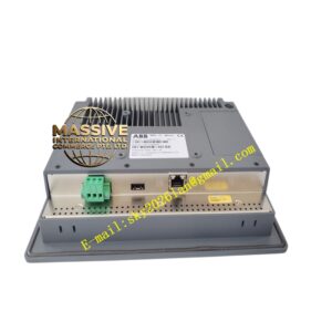
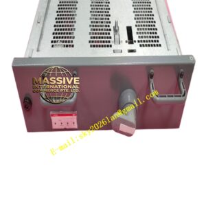
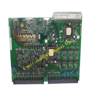
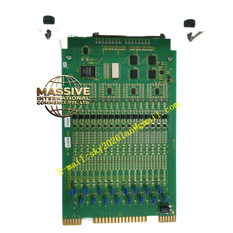
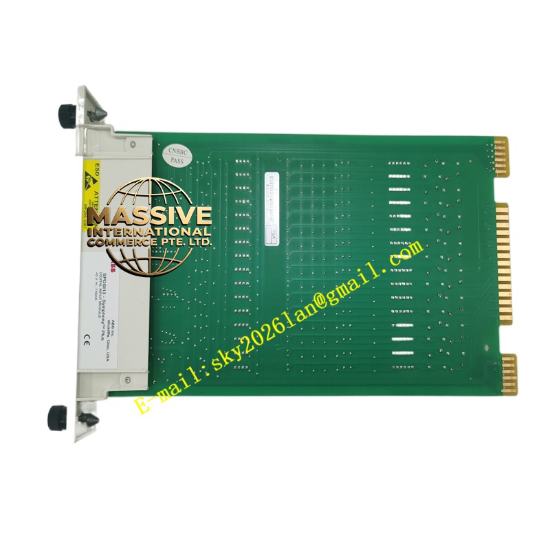
ABB SPDSI13
- Technical Specifications (typical SPDSI13 — 24 V DC version):
- Input Channels: 16 (2 groups × 8)
- Input Voltage: 24 V DC (18–30 V) — threshold ON ≥11 V, OFF ≤5 V
- Input Current: ≈7 mA per channel (when ON)
- Response Time: <10 ms typical; debounce filter 0–127 ms (firmware)
- Isolation: 1500 V AC channel-group-to-backplane
- Power: From S100 bus (5 V logic + 24 V excitation derived from bus PSU)
- Indicators: Run LED (green), Err LED (red), per-group Input Active LED; some have per-channel LED (dim)
- Mounting: On S100 termination unit (TA563/TA566) — DIN rail
- Operating Temp.: 0 °C to +55 °C
- Certifications: CE, UL, cUL, marine
- Functional Features / Application / Material / Structure / Working Principle / Installation / Precautions:
- Wire field contact between Ix (input) and common (Cx) on S100 termination assembly (TA567 for 24 V)
- For N.C. contacts (e.g., E-Stop N.C.): wire accordingly — logic inversion done in controller SW
- In Advant / AC 800M+S100 Gateway config: assign module type = SPDSI13, starting address, debounce time, normal state (N.O./N.C.)
- Precaution: Verify voltage grade — SPDSI13 is 24 V DC — do NOT apply 110/220 V DC to it (some S100 DI modules are 110/220 V DC — different part number e.g., SPDSI23). Keep S100 bus terminated at both ends. For supervised N.C. wiring ensure sense current path exists (some versions require jumper for supervision enable).